Eureka AIR delivers breakthrough ideas for toughest innovation challenges, trusted by R&D personnel around the world.

Knitting machine

A technology of knitting machines and components, applied in the field of sinkers, to achieve the effect of simple structure, small length and saving manufacturing cost

Active Publication Date: 2014-11-26
KARL MAYER STOLL R&D GMBH
View PDF8 Cites 0 Cited by
  • Summary
  • Abstract
  • Description
  • Claims
  • Application Information

AI Technical Summary

Problems solved by technology

[0003]Known complex structure of sinker
Furthermore, there is currently no way to prevent the drive foot of the needle from settling inadvertently under high axial loads on the needle

Method used


Image

  • Knitting machine
  • Knitting machine
  • Knitting machine

Examples


Embodiment Construction

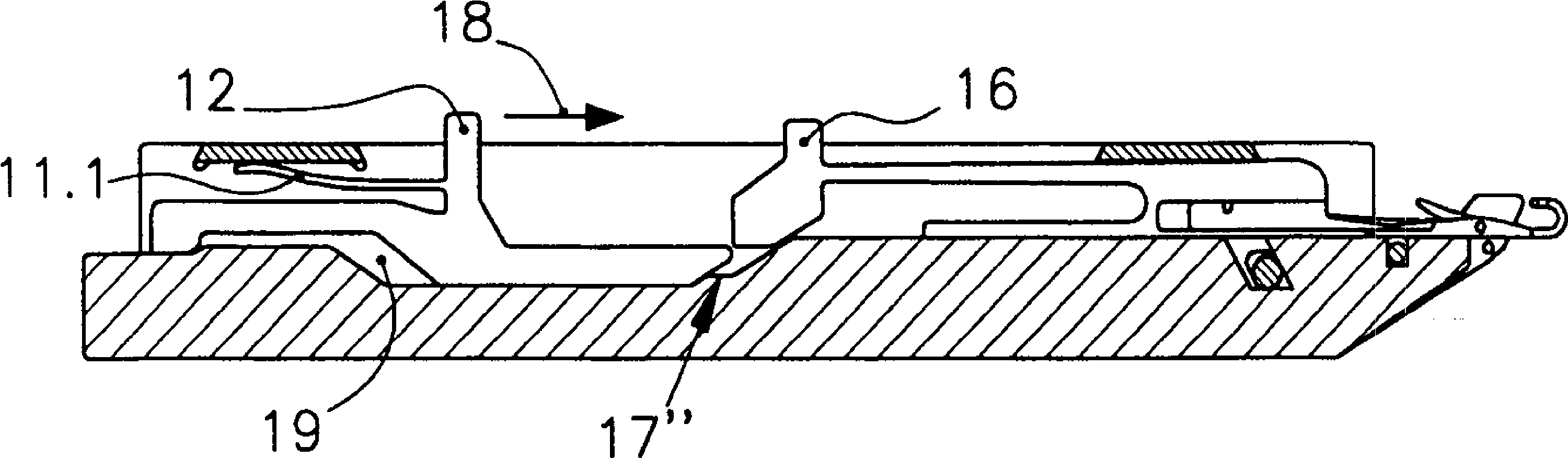
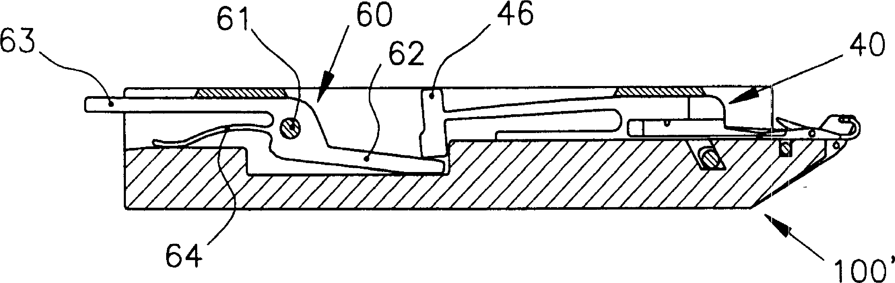
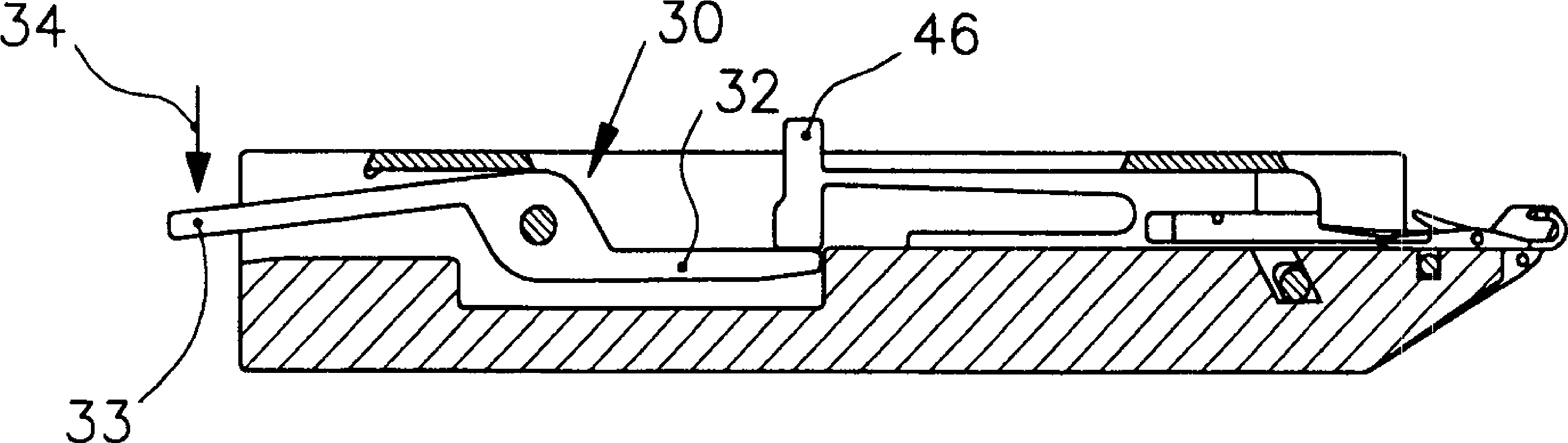
[0030] Figures 1a to 1f Both are sectional views of the functional component groove 110 region of the functional component 100 in which the functional component 10 designed as knitting needles and the sinker 11 are arranged. The cover rail 120 prevents the functional part 10 from coming out of the needle channel 110 together with its adjacent functional parts, and the cover rail 130 prevents the sinker 11 from coming out of the needle channel 110 together with its adjacent sinker. The functional component groove has a recess 19 in the functional component substrate 115 . The sinker 11 is supported on the cover rail 130 via the elastic member 11.1.

[0031] exist Figure 1a , both the functional part 10 and the sinker 11 are in their untouched initial position. The sinker 11 has been moved backwards by means of the positioning feet 12 . The needle hooks 13 of the functional part 10 are in an evenly aligned position (Kammgleeche position). In its rear region, the functiona...


PUM


Abstract

The plate (11) has a drive base (16) lifted over a functional element bed (100) i.e. needle bed, by pivoting the plate around axles by a lifting linkage. A functional element base (115) is formed in two different heights for a functional element (10). The functional element and the plate are pivotably arranged in a common functional element channel (110) of the functional element bed. Lowering of the drive base into the bed is controlled. The drive base is lifted against spring force. The plate is backwardly movable in an inactive starting position over a positioning base (12).

Description

technical field [0001] The invention relates to a sinker (platine) for a functional part of a knitting machine, wherein a drive foot (Antriebsfu®) of the functional part, which sinks into a functional part bed, can be lifted above the functional part bed by means of the sinker. [0002] Background technique [0003] Such sinkers are known for functional parts in the form of needles of knitting machines, especially flat knitting machines. For example, DE 687 608 describes a sinker which, for example, lifts the drive foot of the knitting needle, which is sunk into the functional part, above the functional part bed so that the drive foot can be clamped by the cam (Schlosskurve) of the knitting system live. The path that the drive foot takes through the cam (Strickschloss) determines which function the needle is to perform, that is, whether the needle forms a loop, lays a tuck (Fang) or rests in an untouched position. [0004] Known sinkers have complex structures. Furthermor...

Claims


Application Information

Patent Timeline
Patent Type & Authority Patents(China)
IPC IPC(8): D04B15/06
CPCD04B15/68
Inventor A.迪博尔德G.格茨S.迈尔J.莫尔
Owner KARL MAYER STOLL R&D GMBH
Why Eureka
Eureka Blog
Learn More