Eureka AIR delivers breakthrough ideas for toughest innovation challenges, trusted by R&D personnel around the world.

Installation device for deepwater stand pipes and underwater facilities

A technology for installing devices and facilities, which is applied in the direction of pipeline laying and maintenance, mechanical equipment, pipes/pipe joints/fittings, etc. It can solve problems such as poor safety and economy, complicated installation process, and many underwater operations. Utilization, simplification of installation process, and simple structure

Inactive Publication Date: 2011-11-09
CHINA NAT OFFSHORE OIL CORP +2
View PDF4 Cites 10 Cited by
  • Summary
  • Abstract
  • Description
  • Claims
  • Application Information

AI Technical Summary

Problems solved by technology

[0003] The laying of submarine pipelines needs to be carried out on the pipe-laying ship. When the traditional S-type pipe-laying ship installs the riser, due to the existence of the stern stinger, it is difficult for the pipe-laying ship to approach the installation platform, and when installing underwater facilities , it is also difficult for large underwater facilities to pass through the stinger; due to the many underwater operations during the installation process and the difficulty in tension conversion, it is difficult for the S-type pipe-laying vessel to independently install the riser, and it needs to cooperate with underwater robots and multiple auxiliary vessels Complete, the installation process is complicated, and the safety and economy are poor

Method used


Image

  • Installation device for deepwater stand pipes and underwater facilities
  • Installation device for deepwater stand pipes and underwater facilities
  • Installation device for deepwater stand pipes and underwater facilities

Examples


Embodiment Construction

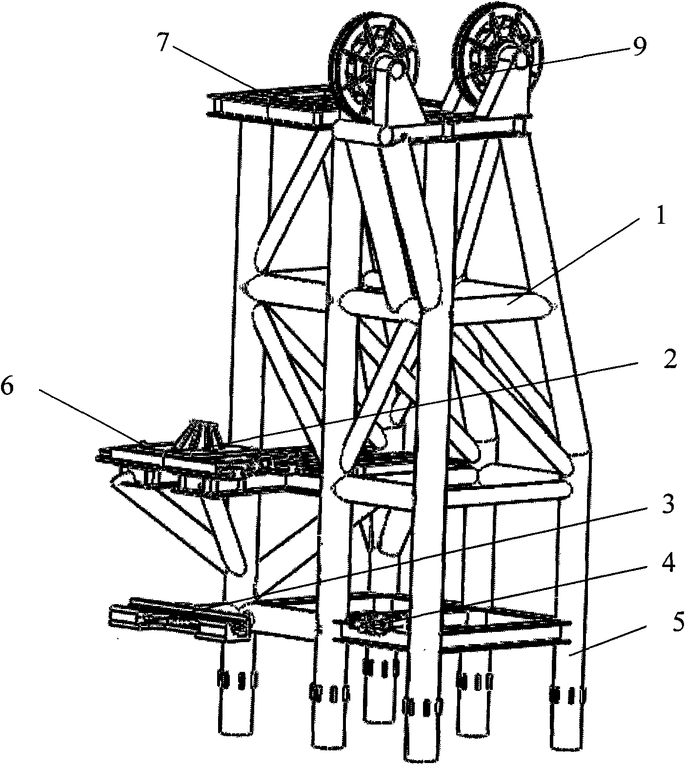
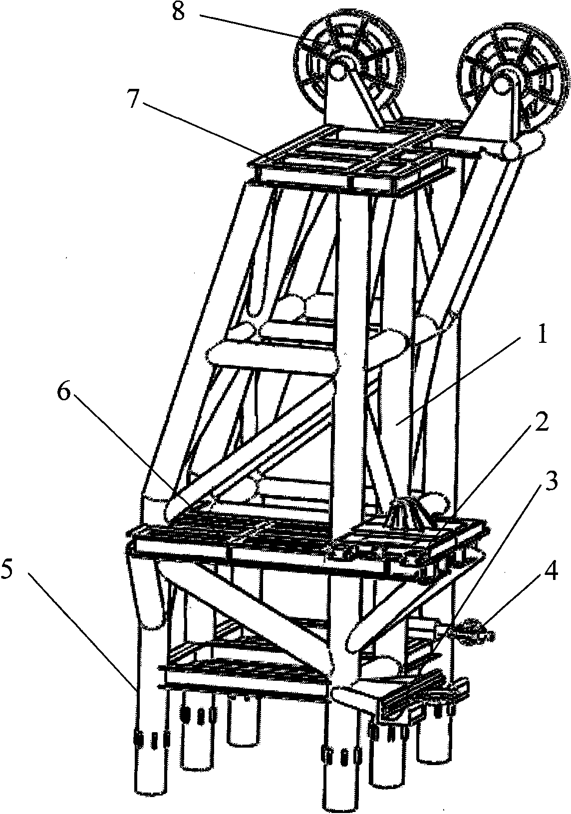
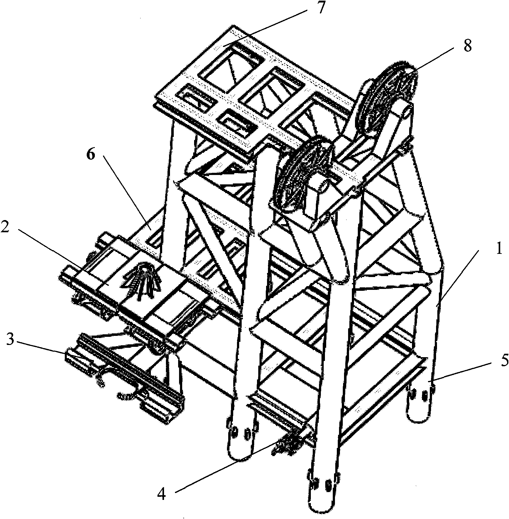
[0024] Such as Figure 1-Figure 3 As shown, the present invention includes: the main support frame is the main body tower 1, and the whole is a frame-type steel structure composed of several main support legs 5 connected by welding through struts. The main support legs of the main body tower 1 in this embodiment 5 is five, and the overall shape is trapezoidal, and each support leg 5 adopts welding mode to be installed on the deck of ship's side with the temporary support leg on the ship. The uppermost layer of the main tower 1 is welded to fix a top working platform 7, which is welded by I-beam with better bending resistance, and is mainly used for horizontally limiting large underwater facilities and providing an operating platform. The left side of the top working platform 7 is connected with two pairs of bearing blocks by bolts and two top guide pulleys 8 are installed, which are used for space guiding the winch cables. A cantilever-type supporting working platform 6 is fi...


PUM


Abstract

The invention discloses an installation device for deepwater stand pipes and underwater facilities, which comprises a main body tower frame. The top of the main body tower frame is provided with a top work platform. A plurality of guide pulleys are arranged on one side of the top work platform, a support work platform is arranged in the middle of the main body tower frame. A stand pipe fixing device is arranged at the front end of the support work platform. A stand pipe limiting device is arranged on a main support pin which is arranged on one side of the lower end of the main body tower frame. A limit device of a rendering winch cable is arranged on the other side of the lower end of the main body tower frame. A technical process for installing the stand pipes and the underwater facilities via an S-shaped pipe-laying ship is simplified, and the integration of pipe laying, installation of the stand pipes and the underwater producing systems via the S-shaped pipe-laying ship is realized. The installation device for the deepwater stand pipes and the underwater facilities is simply structured. The utilization maximum of the pipe-laying ship is realized and the pipe-laying ship can berepeatedly utilized on condition that the self-structure of the S-shaped pipe-laying ship is affected least.

Description

technical field [0001] The invention relates to an installation device, in particular to a deep-water riser and underwater facility installation device used for installing risers and underwater facilities on a pipe-laying ship, and belongs to the field of offshore oil engineering. Background technique [0002] At present, offshore oil and gas exploration and development have expanded from shallow seas to deep seas, and are focusing on oil and gas reservoirs with water depths exceeding 3,000 meters that are rich in oil, gas and gas hydrate resources. Among them, the hoisting and traction during the installation of deepwater risers and underwater facilities is a relatively complicated and extremely important part of deepwater development projects. [0003] The laying of submarine pipelines needs to be carried out on the pipe-laying ship. When the traditional S-type pipe-laying ship installs the riser, due to the existence of the stern stinger, it is difficult for the pipe-layi...

Claims


Application Information

Patent Timeline
Patent Type & Authority Applications(China)
IPC IPC(8): F16L1/12
Inventor 姜锡肇何宁段梦兰王懿李丽娜王辉王波
Owner CHINA NAT OFFSHORE OIL CORP
Why Eureka
Eureka Blog
Learn More