
Optical membrane

An optical film and light-transmitting substrate technology, applied in optics, optical components, nonlinear optics, etc., can solve the problems of partial sticking of the optical film of the prism sheet, abnormal local area of ​​the display screen, affecting the display quality of the display panel, etc. Achieve the effect of avoiding sticking, reducing moire phenomenon and increasing contact area

Inactive Publication Date: 2011-11-09
CORETRONIC
View PDF14 Cites 20 Cited by
  • Summary
  • Abstract
  • Description
  • Claims
  • Application Information

AI Technical Summary

Problems solved by technology

[0004] However, the crest line on the top of the columnar prism and the valley lines formed between two adjacent columnar prisms are very obvious and arranged at regular intervals, so it is easy to match the display on the prism sheet or the enhancement film. Panels (such as liquid crystal display panels) form moire, which affects the display quality of the display panel
In addition, the sharp corners formed by the cylindrical prisms at the ridges and the adjacent optical elements are also prone to wear or scratches
Furthermore, since the heights of each columnar prism are the same, the prism sheet is prone to local adhesion to the adjacent optical film, resulting in local abnormalities in the display screen.

Method used


Image

  • Optical membrane
  • Optical membrane
  • Optical membrane

Examples


Embodiment Construction

[0057] The aforementioned and other technical contents, features and effects of the present invention will be clearly presented in the following detailed description of a preferred embodiment with reference to the drawings. The directional terms mentioned in the following embodiments, such as: up, down, left, right, front or back, etc., are only directions referring to the attached drawings. Accordingly, the directional terms are used to illustrate and not to limit the invention.

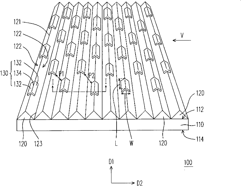
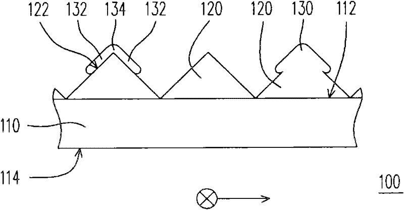
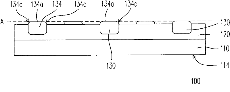
[0058] Figure 1A is a schematic diagram of an optical film according to an embodiment of the present invention, and Figure 1B for Figure 1A The cross-sectional view of the optical diaphragm along the I-I line, Figure 1C for Figure 1A Side view of the optical film along direction V. Please refer to Figure 1A , Figure 1B and Figure 1C , the optical film 100 of this embodiment can be applied to a light source module or a backlight module of a liquid crystal display to enhance the brightness...


PUM


Abstract

The invention provides an optical membrane. The membrane comprises a transmission basal plate, a plurality of strip bumps and a plurality of bump structures, wherein the transmission basal plate is provided with a first surface and a second surface which are oppositely arranged; the strip bumps are arranged on the first surface, each strip bump is provided with two strip lateral faces; the bump structures are arranged on ridges of the strip bumps, each bump structure is provided with a raised end and two wing parts; the raised end is protruded from the ridge of corresponding strip bump; the two wing parts are respectively positioned on the two strip lateral faces of the corresponding strip bump, each wing part extends from the raised end to the position between the ridge and a valley line; the length of the bump structure in the direction parallel to the extending direction of the ridge is L, and the width of the bump structure in the direction vertical to the ridge is W, and L / W is more than or equal to 1.2. By the optical membrane, at least one of veins, local adhesion, scrape and abrasion of the optical membrane with other optical elements can be effectively improved.

Description

【Technical field】 [0001] The invention relates to an optical film. 【Background technique】 [0002] With the progress of the optoelectronic industry, the requirements for the light shape provided by the light source module are gradually increasing. At this time, a variety of optical films have been developed to meet the various needs of the light shape. These optical films include diffusion sheets, brightness enhancement films (BEF), such as prism sheets, lens arrays, etc. Among them, the prism sheet used as the enhancement film uses the light-emitting facets of several cylindrical prisms to select the light rays with different incident directions. Generally speaking, light incident on the bottom of the lenticular prism at an angle of about 60 degrees will be refracted by the lenticular prism to pass through the prism, and exit in a direction roughly perpendicular to the bottom of the lenticular prism. In addition, light that is too large or too small to be 60 degrees will...

Claims


Application Information

Patent Timeline
Patent Type & Authority Applications(China)
IPC IPC(8): G02B6/00G02F1/13357
CPCG02B6/0038G02B6/0053
Inventor 萧增科翁兆泓赵伟忠刘昌成王必昌
Owner CORETRONIC
Learn More