Magnetic head spring plate structure

A magnetic head and shrapnel technology, which is applied in the direction of instruments, inductive record carriers, computer components, etc., can solve problems such as uneven locking pressure, damaged solder, and damaged parts, so as to avoid uneven pressure, save time and effort for assembly, and stabilize The effect of pressure

Active Publication Date: 2011-11-09
CASTLES TECH
View PDF8 Cites 12 Cited by
  • Summary
  • Abstract
  • Description
  • Claims
  • Application Information

AI Technical Summary

Problems solved by technology

[0005] However, the known magnetic head shrapnel are directly fixed on the base body by screw locking or soldering. Although it is the simplest and cost-effective way, when the magnetic head or the magnetic head shrapnel needs to be disassembled and replaced due to damage, It takes more time and manpower to remove the screws or destroy the solder, which is the biggest disadvantage of this fixing method
[0006] In addition, when the magnetic head shrapnel is fixed on the base body by means of screw locking in the prior art, it is easy to have uneven locking pressure, resulting in poor reading of the card and even damage to the parts.

Method used


Image

  • Magnetic head spring plate structure
  • Magnetic head spring plate structure
  • Magnetic head spring plate structure

Examples


Embodiment Construction

[0048] In order to further explain the technical means and effects that the present invention adopts to achieve the intended purpose of the invention, below in conjunction with the accompanying drawings and preferred embodiments, the specific implementation, structure, characteristics and effects of the magnetic head shrapnel structure proposed according to the present invention are as follows: Details are as follows.

[0049] The aforementioned and other technical contents, features and effects of the present invention will be clearly presented in the following detailed description of preferred embodiments with reference to the drawings. Through the description of specific implementation methods, the technical means and effects of the present invention to achieve the intended purpose can be understood more deeply and specifically, but the attached drawings are only for reference and description, and are not used to explain the present invention limit.

[0050] Please also se...


PUM


Abstract

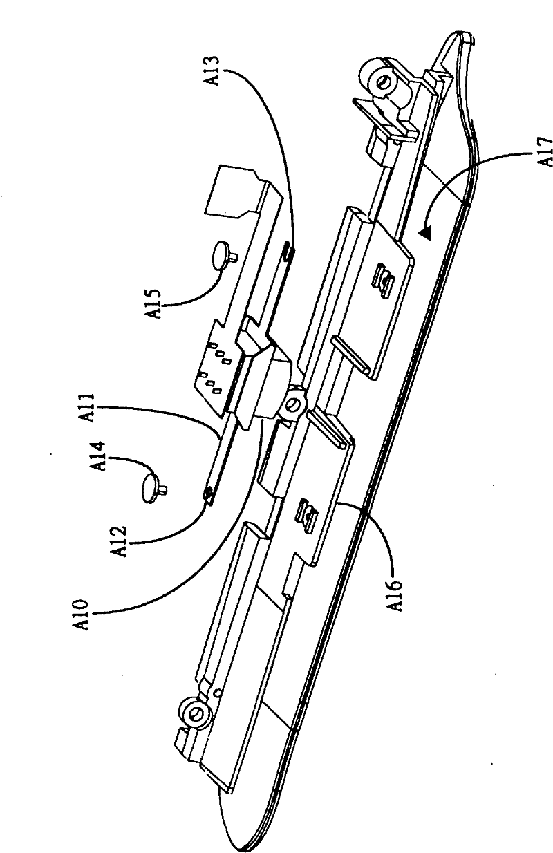
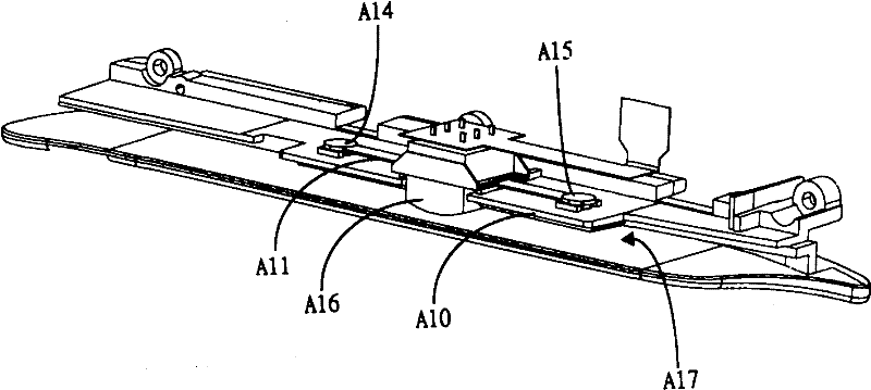
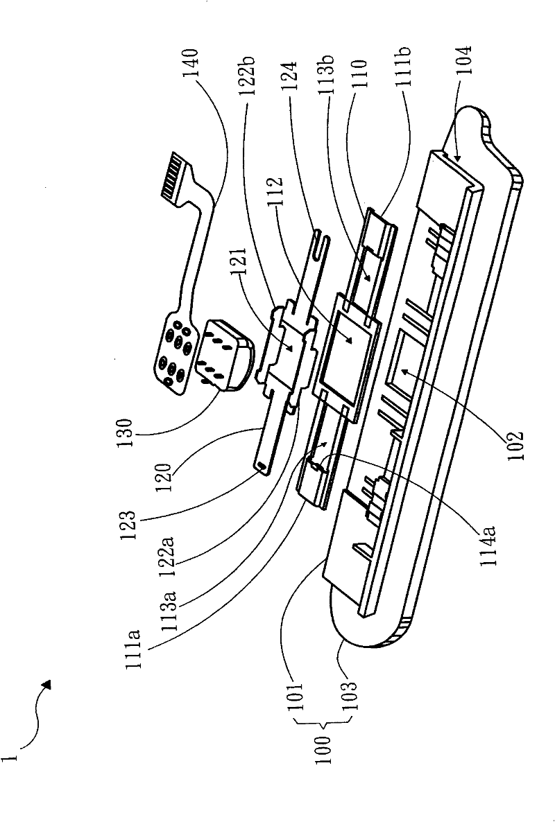
The invention relates to a magnetic head spring plate structure which comprises a seat body, a fixed base board, a clamping spring plate and a magnetic head module, wherein the seat body comprises a first seat board and a second seat board; the first seat board is provided with a first through hole; a clearance is arranged between the first seat board and the second seat board; the fixed base board is arranged on the first seat board, the center of the fixed base board is provided with a second through hole, and both sides of the second through hole are respectively provided with a third through hole; the clamping spring plate is stacked on the fixed base board, the center of the clamping spring plate is provided with a fourth through hole, and both ends of the clamping spring plate respectively penetrate through the third through holes so that the clamping spring plate is fixed onto the fixed base board; and the magnetic head module penetrates through the first through hole, second through hole and fourth through hole, and used for contacting a card so as to read information.

Description

technical field [0001] The invention relates to a magnetic head shrapnel structure, in particular to a magnetic head shrapnel structure with a fixing method. Background technique [0002] It has become an indispensable part of modern social life to use various financial magnetic cards as payment and transfer media in daily life. The application of other magnetic cards is also becoming more and more widespread, such as magnetic card access control locks, identification magnetic cards, etc., so the magnetic head fixing structure of the card reader used to read the magnetic card tape, with the expansion of the use of magnetic cards, Also more important. [0003] When the magnetic head of the card reader reads the tape data of the magnetic card, they must be closely attached to each other so that the magnetic head can effectively read the data of the tape. Therefore, the magnetic head must be combined with an elastic element. The magnetic head can provide a moderate relative m...

Claims


Application Information

Patent Timeline
Patent Type & Authority Applications(China)
IPC IPC(8): G06K7/08
Inventor 管军伟罗义雄郑凯宇
Owner CASTLES TECH
Why Eureka
Try Eureka