
Radome, antenna device and radar apparatus

A technology of antenna device and radome, which is applied in the field of radome and can solve problems such as inability to radiate radio waves

Active Publication Date: 2011-11-09
FURUNO ELECTRIC CO LTD
View PDF6 Cites 6 Cited by
  • Summary
  • Abstract
  • Description
  • Claims
  • Application Information

AI Technical Summary

Problems solved by technology

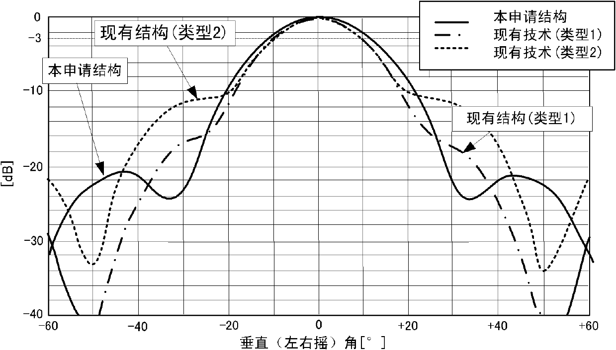
[0006] However, in the structures of the radome shown in Patent Document 1 and Patent Document 2, it is not possible to expand the angular range in which the radio wave in the vertical direction is equal to or higher than a predetermined level (vertical direction directivity).
Therefore, when the ship on which the antenna device is installed shakes, radio waves at an effective level may not be radiated in the target direction.

Method used


Image

  • Radome, antenna device and radar apparatus
  • Radome, antenna device and radar apparatus
  • Radome, antenna device and radar apparatus

Examples


Embodiment Construction

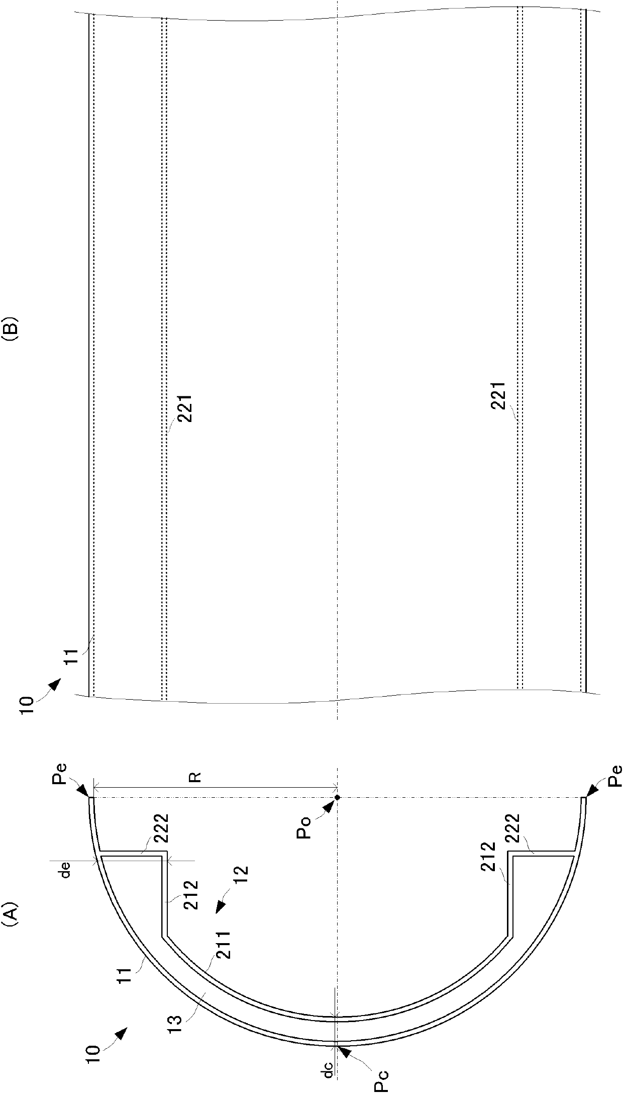
[0037] A radome according to a first embodiment of the present invention will be described with reference to the drawings. In addition, the case where radio waves are radiated by the antenna device including the radome will be described below as an example, but the same effect can be obtained also when radio waves are received from the outside. figure 1 (A) is a side sectional view showing the structure of the radome 10 of this embodiment, figure 1 (B) is a partial front view of the radome 10 .

[0038] The shape of the front view of the radome 10 is a long shape (rectangular), and the side section is as follows: figure 1 As shown in (A), it consists of a semicircle. The radome 10 includes an outer wall 11 and an inner wall 12 . The outer wall 11 and the inner wall 12 are formed of the same dielectric material.

[0039] The outer wall 11 constitutes the outer wall surface of the radome 10, has a predetermined thickness, and is formed in a semicircular shape with a radius R...


PUM


Abstract

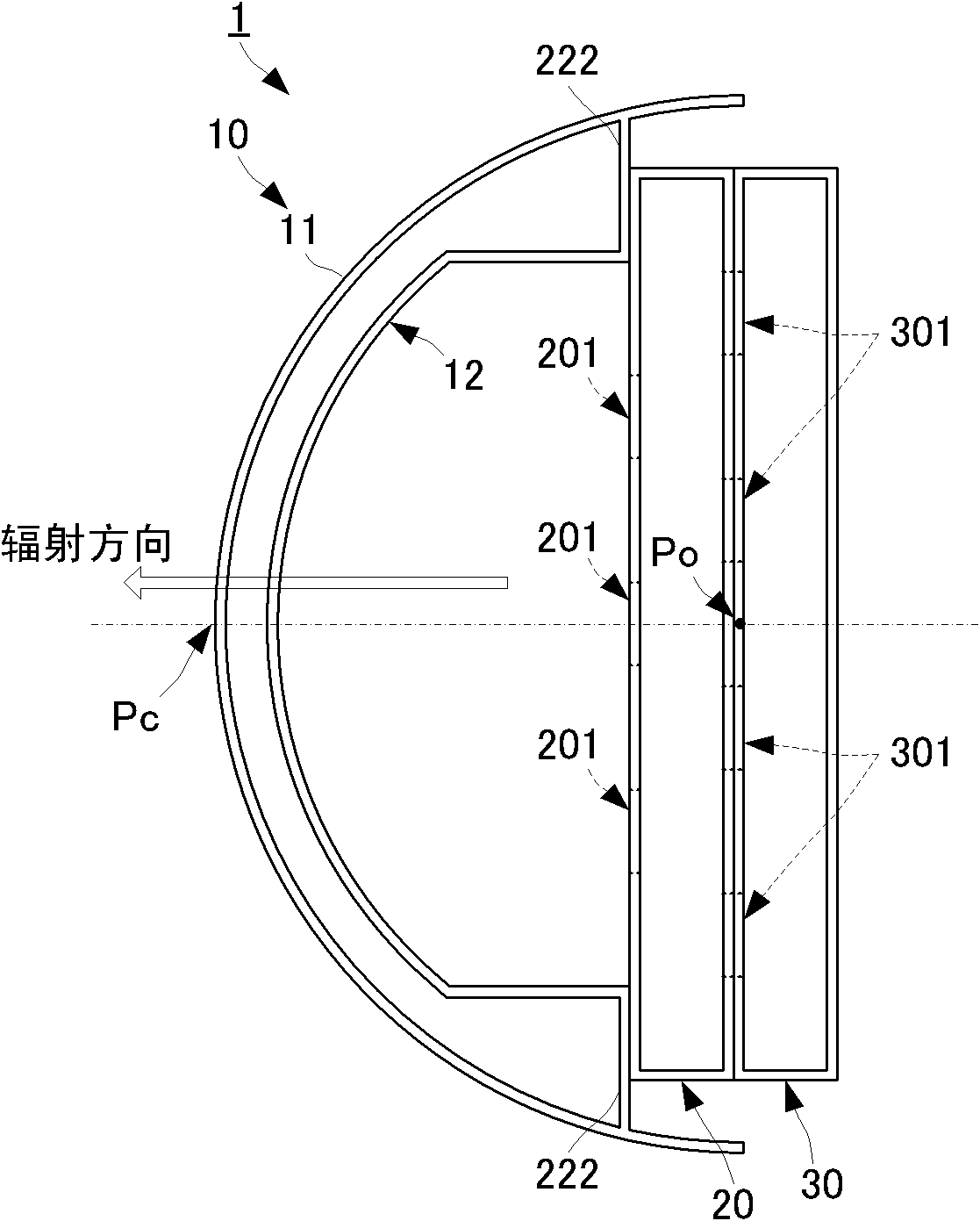
The present invention provides a radome that can have a wide vertical radiation patter, as well as an antenna device provided with the radome, and a radar apparatus provided with the antenna device. The radome (10) includes an outer wall (11) having a side cross-section formed in a substantially semi-circular shape, and an inner wall (12) arranged at the inner side of the outer wall. The inner wall includes a first inner wall (211) and second inner walls (212). The first inner wall is arranged, in the side view, so as to be spaced from the outer wall by the fixed smallest gap (dc) within a range from a midpoint (Pc) on the circumference of the outer wall to prescribed distance positions toward both ends (Pe). Each second inner wall is composed of a flat plate which has an end connected with the end of the first inner wall and has a plane parallel to the straight line between the midpoint (Pc) and the center (Po). Therefore, the smallest gap (de) between the outer wall and the inner wall near the ends (Pe) of the outer wall becomes wider than the smallest gap (dc) between the outer wall and the inner wall near the midpoint (Pc) of the outer wall.

Description

technical field [0001] The present invention relates to an antenna device for transmitting and receiving radio waves and a radar device including the antenna device, and more particularly to a radome for protecting an antenna of the antenna device. Background technique [0002] Conventionally, a radar device is provided with an antenna that receives a supply of radiating power, radiates (emits) radio waves of a predetermined frequency, and receives external radio waves such as reflected waves of the radiated radio waves. Furthermore, in order to protect such an antenna from the external environment, a radome having a shape to cover the antenna is used, and an antenna device is constituted by the antenna and the radome. [0003] As a structure for protecting the antenna, the radome also has a wall surface in the maximum radiation direction of the antenna. However, since reflection of radio waves or the like occurs on the wall surface of the radome, its influence must be supp...

Claims


Application Information

Patent Timeline
Patent Type & Authority Applications(China)
IPC IPC(8): H01Q1/42G01S13/02
CPCH01Q15/08H01Q1/42H01Q15/02H01Q19/06
Inventor 宫川哲也箟耕治
Owner FURUNO ELECTRIC CO LTD
Learn More