Bottle mounting tag
A technology for installation and labeling, which can be used in identification devices, stamps, instruments, etc., and can solve problems such as decreased reading reliability.
- Summary
- Abstract
- Description
- Claims
- Application Information
AI Technical Summary
Problems solved by technology
Method used
Image
Examples
no. 1 example
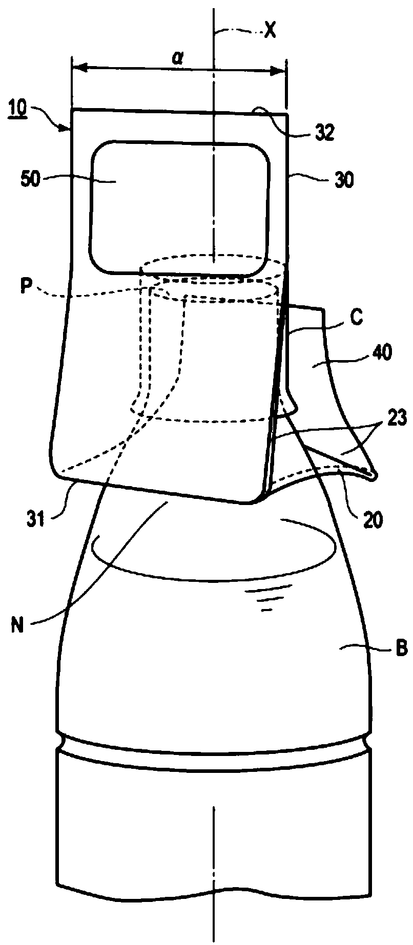
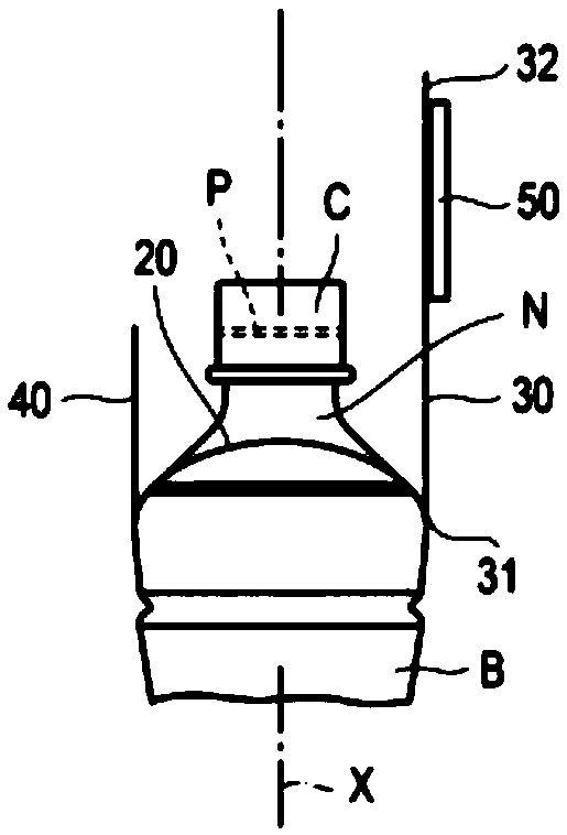
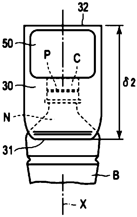
[0052] figure 1 It is a perspective view showing a state where the bottle attachment label 10 according to the first embodiment is attached to a plastic bottle (polyester bottle) B, figure 2 It is a side view showing a state in which the bottle mounting label (bottle label) 10 in the first embodiment is mounted on a plastic bottle B, image 3 It is a front view showing a state in which the bottle attachment label 10 in the first embodiment is attached to a plastic bottle B, Figure 4 It is a developed view showing the bottle attachment label 10 in the first embodiment. In addition, in Figure 1 to Figure 3 In, N shows the bottleneck of the plastic bottle B, and the mouth part P is provided in the upper end of the bottleneck N. The mouth P is sealed by a cap C. also, Figures 1 to 3 The middle X shows the central axis of the plastic bottle B.
[0053] Such as figure 1 As shown, the bottle attachment label 10 is formed by bending a substantially rectangular sheet (resin ...
no. 2 example
[0070] Figure 8 It is a perspective view showing a state where the bottle attachment label 10A according to the second embodiment is attached to a plastic bottle B, Figure 9 It is a perspective view showing the bottle attachment label 10A according to the second embodiment, Figure 10 It is a development view which shows the label 10A for bottle attachments concerning 2nd Example. Additionally, in these Figure 8 to Figure 10 in, with figure 1 The same symbols are assigned to the same functional parts, and their detailed descriptions are omitted.
[0071] Such as Figure 8 As shown, the bottle attachment label 10A is attached to the neck N of the plastic bottle B. As shown in FIG. 10 A of labels for bottle attachments have the base (base) part 60 of cylindrical table shape. Such as Figure 9 As shown, an RFID tag 50 is provided on the outer peripheral surface of the base portion 60 . Such as Figure 10 As shown, the base part 60 has the base piece (fixing part) 61 w...
no. 3 example
[0078] Figure 11 It is a perspective view showing a state where the bottle attachment label 10B according to the third embodiment is attached to a plastic bottle B, Figure 12 It is a perspective view which shows the bottle attachment label 10B in this Example. Additionally, in these Figure 11 and Figure 12 in, with figure 1 Parts with the same functions are given the same symbols, and their detailed descriptions are omitted.
[0079] Such as Figure 11 As shown, the bottle attachment label 10B is attached to the neck N of the plastic bottle B. As shown in FIG. The bottle-attaching label 10B has a double-layer cylinder 70 made of a resin material. Such as Figure 12 As shown, an RFID tag 50 is disposed on the outer peripheral surface of the double-layer cartridge 70 . The double-layer cylinder 70 has a cylindrical outer cylinder 70, an inner cylinder (fixed portion) 72 coaxially formed inside the outer cylinder 71, and a seal opening closed on the top of the outer c...
PUM
 Abstract
Description
Claims
Application Information
 - R&D
- Intellectual Property
- Life Sciences
- Materials
- Tech Scout
- Unparalleled Data Quality
- Higher Quality Content
- 60% Fewer Hallucinations
Browse by: Latest US Patents, China's latest patents, Technical Efficacy Thesaurus, Application Domain, Technology Topic, Popular Technical Reports.
© 2025 PatSnap. All rights reserved.Legal|Privacy policy|Modern Slavery Act Transparency Statement|Sitemap|About US| Contact US: help@patsnap.com


