Ultrasonic probe and ultrasonic diagnostic apparatus
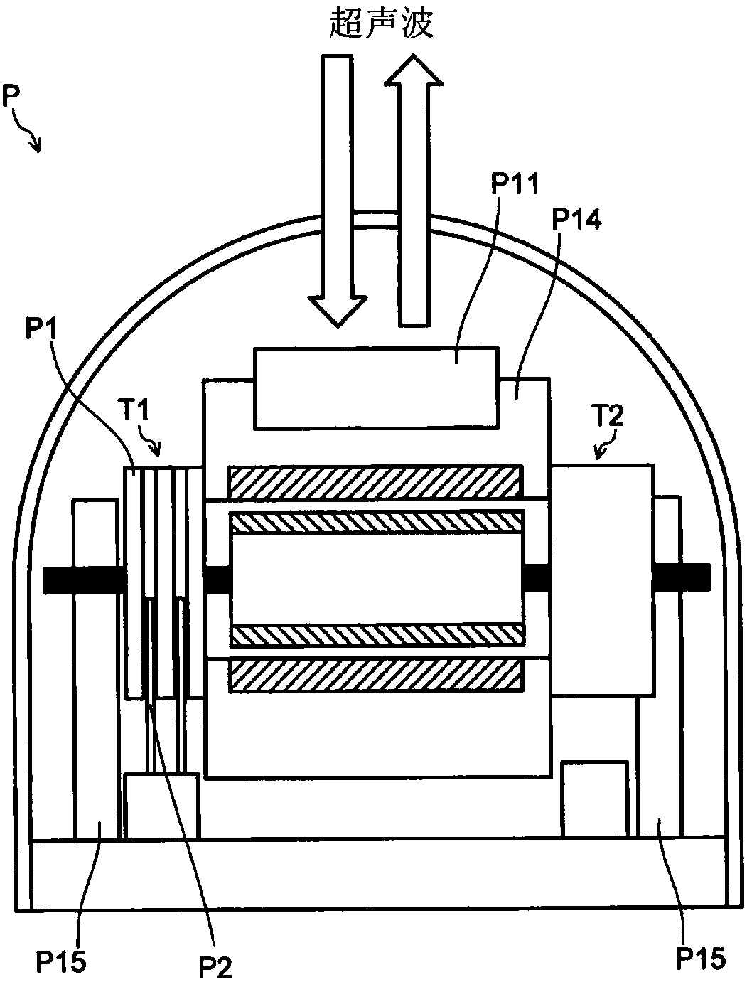
An ultrasonic and detector technology, which is applied in the field of ultrasonic detectors and ultrasonic diagnostic devices, can solve problems such as poor contact, brush P2 slip ring P1 wear, unreliable electrical signals, etc., and achieve reliable sending and receiving effects
- Summary
- Abstract
- Description
- Claims
- Application Information
AI Technical Summary
Problems solved by technology
Method used
Image
Examples
no. 1 approach
[0042] Below, refer to Figure 2 ~ Figure 6 , the configuration of the ultrasonic probe 10 according to the first embodiment will be described. The ultrasonic probe 10 according to the present embodiment is applied to the ultrasonic diagnostic apparatus 1 as described above, for example.
[0043] [Configuration of Ultrasonic Diagnostic Device]
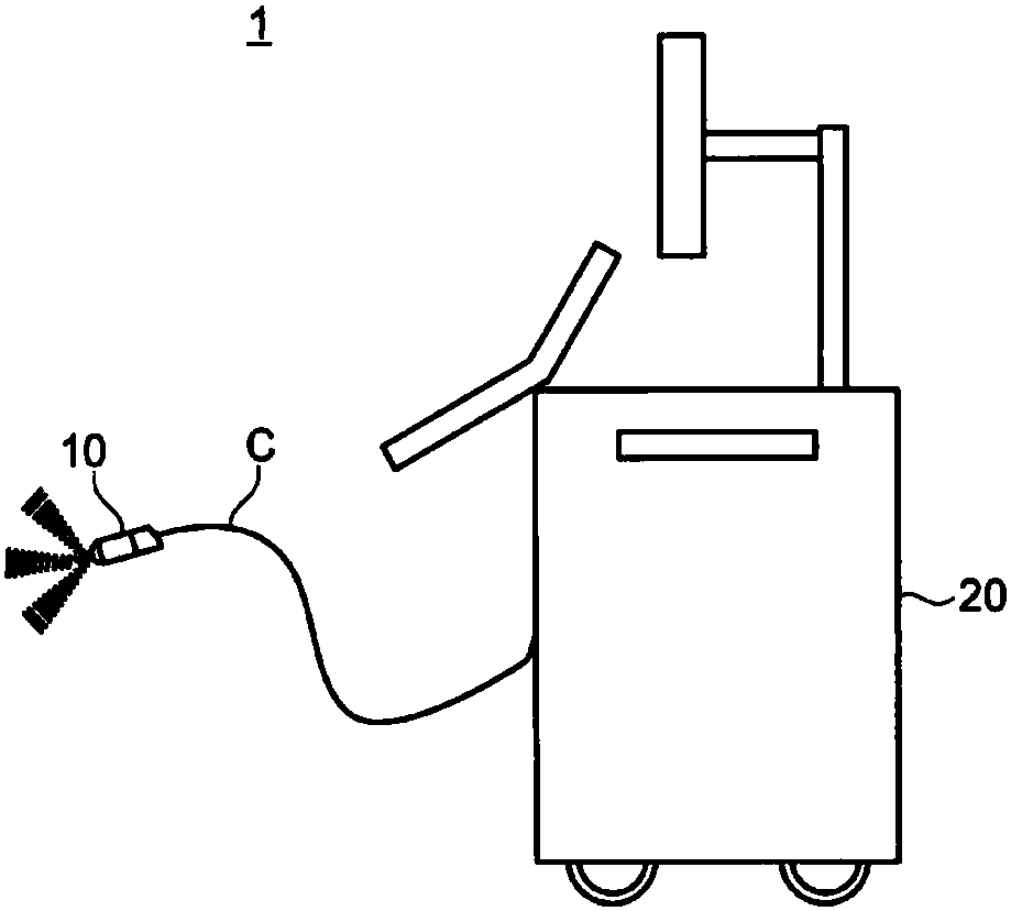
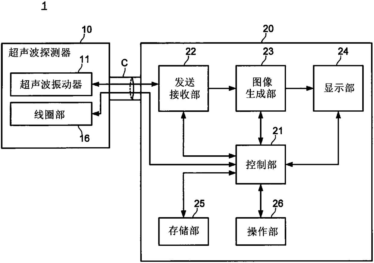
[0044] figure 2 It is a diagram showing the appearance of the ultrasonic diagnostic apparatus 1 according to the present embodiment. image 3 It is a block diagram showing an example of the overall configuration of the ultrasonic diagnostic apparatus 1 according to the present embodiment.
[0045] The ultrasonic diagnostic apparatus 1 according to the present embodiment is configured by attaching the ultrasonic probe 10 to the main body 20 of the ultrasonic diagnostic apparatus 1 . In addition, the main body 20 and the ultrasonic probe 10 are electrically connected via a cable C. As shown in FIG.
[0046] In addition, the ultraso...
no. 2 approach
[0095] Below, refer to Figure 8 ~ Figure 9 , an example of the configuration of the ultrasonic probe 10 according to the second embodiment will be described.
[0096] The ultrasonic probe 10 according to the present embodiment differs from the first embodiment in that a plurality of highly rigid rotating bodies 17 f are arranged together with the rotating contacts 17 c in the annular guide groove A of the rotating electrical connector 17 . In addition, description is omitted for the same configuration as that of the first embodiment (hereinafter, the same applies to other embodiments).
[0097] Figure 8 , Figure 9 are respectively the same as those of the first embodiment Figure 5 , Figure 6 The corresponding drawings (side view and cross-sectional view of the rotary electrical connector 17 ) are diagrams showing an example of the configuration of the rotary electrical connector 17 according to the present embodiment.
[0098] As described above, the rotary contact p...
no. 3 approach
[0106] Below, refer to Figure 10 ~ Figure 12 , an example of the configuration of the ultrasonic probe 10 according to the third embodiment will be described.
[0107] In the ultrasonic probe 10 according to the present embodiment, the rotating electrode 17a and the fixed electrode 17b are arranged to face each other along the extending direction of the rotating shaft, and are rotatably supported in a region where the rotating electrode 17a and the fixed electrode 17b face each other. The orbital plate 17g of the rotary contact 17c is different from the first embodiment.
[0108] Figure 10 , Figure 11 are respectively the same as those of the first embodiment Figure 5 , Figure 6 The corresponding drawings (side view and cross-sectional view of the rotary electrical connector 17 ) are diagrams showing an example of the configuration of the rotary electrical connector 17 according to the present embodiment. Figure 12 It is an exploded view of the rotary electrical con...
PUM
 Abstract
Description
Claims
Application Information
 - R&D
- Intellectual Property
- Life Sciences
- Materials
- Tech Scout
- Unparalleled Data Quality
- Higher Quality Content
- 60% Fewer Hallucinations
Browse by: Latest US Patents, China's latest patents, Technical Efficacy Thesaurus, Application Domain, Technology Topic, Popular Technical Reports.
© 2025 PatSnap. All rights reserved.Legal|Privacy policy|Modern Slavery Act Transparency Statement|Sitemap|About US| Contact US: help@patsnap.com


