Rotary brush for floor cleaner and base assembly of floor cleaner using the rotary brush

A technology of cleaners and rotating brushes, which is used in cleaning floors, cleaning equipment, machine parts, etc., and can solve problems such as impossible removal, complexity, and overturning of the main body

Inactive Publication Date: 2011-11-16
SUZHOU HAAN TECH +1
View PDF7 Cites 22 Cited by
  • Summary
  • Abstract
  • Description
  • Claims
  • Application Information

AI Technical Summary

Problems solved by technology

[0003] However, when hair strands or thread ends in the dust come into contact with the bristles, they will wind up on the bristles or the rotating shaft, so it is very troublesome to remove them by cutting them off with a knife, or pulling them out one by one by hand. And even if it is removed in this w

Method used


Image

  • Rotary brush for floor cleaner and base assembly of floor cleaner using the rotary brush
  • Rotary brush for floor cleaner and base assembly of floor cleaner using the rotary brush
  • Rotary brush for floor cleaner and base assembly of floor cleaner using the rotary brush

Examples


Embodiment Construction

[0080] Hereinafter, preferred embodiments of the present invention will be described with reference to the drawings, but the same reference numerals will be assigned to the same parts as conventional ones, and detailed descriptions will be omitted.

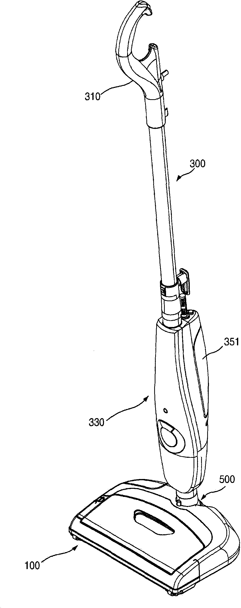
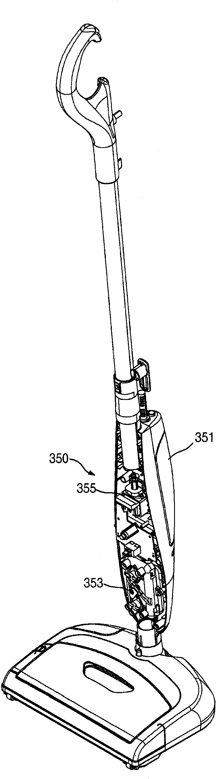
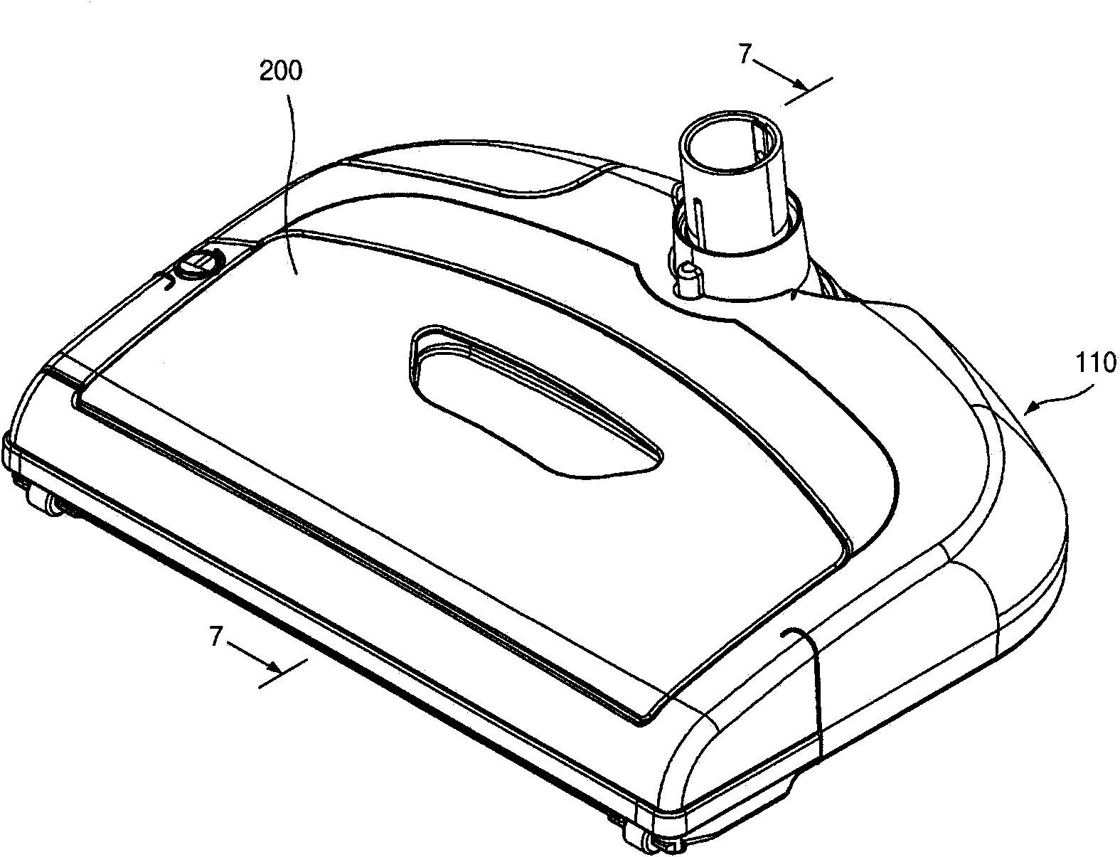
[0081] figure 1 It is a perspective view of a steam sweeper related to a preferred embodiment of the present invention, figure 2 for expressing figure 1 A perspective view of the instantaneous jet steam generating unit in , image 3 for figure 1 An enlarged perspective view of the base assembly of the, Figure 4 for from image 3 The three-dimensional view after separating the dust bucket, Figure 5 for from Figure 4 A perspective view after further separating the locking parts, Image 6 for image 3 The exploded perspective view of Figure 7 for along image 3 The sectional view seen on line 7-7, Figure 8 for image 3 The upward perspective view of Figure 9 is a perspective view of the bottom surface of the upper...


PUM


Abstract

The invention relates to a rotary brush for a floor cleaner and a base assembly of the floor cleaner using the rotary brush. Hairs or wire ends can be prevented from completely winding a rotary shaft of the rotary brush or winding brush hairs and from being removed difficultly.

Description

technical field [0001] The invention relates to a rotating brush for a floor cleaner and a base assembly for the floor cleaner using the rotating brush, which prevents hair or thread ends from being completely entangled on the rotating shaft or bristles of the rotating brush during cleaning and is difficult to remove. Background technique [0002] Conventionally, a rotating brush for a floor cleaner has at least two rows of bristles along the longitudinal direction of the rotating shaft, so that the bristles function as a broom for sweeping dust and the like. [0003] However, when hair strands or thread ends in the dust come into contact with the bristles, they will wind up on the bristles or the rotating shaft, so it is very troublesome to remove them by cutting them off with a knife, or pulling them out one by one by hand. And even if it is removed in this way, it is impossible to completely remove it because it is completely attached to the bristles or the rotating shaft...

Claims


Application Information

Patent Timeline
IPC IPC(8): A47L11/40A47L11/282
CPCA47L11/4041A47L11/4044A47L11/4069
Inventor 韩京姬
Owner SUZHOU HAAN TECH
Why Eureka
Try Eureka