Stamping-laminating apparatus and method
一种设备、冲压工件的技术,应用在冲压-层叠设备领域,能够解决芯片耗费时间、生产率降低等问题
- Summary
- Abstract
- Description
- Claims
- Application Information
AI Technical Summary
Problems solved by technology
Method used
Image

Examples
no. 1 approach
[0028] will now refer to Figure 4 to Figure 9B A first embodiment of the present invention will be described.
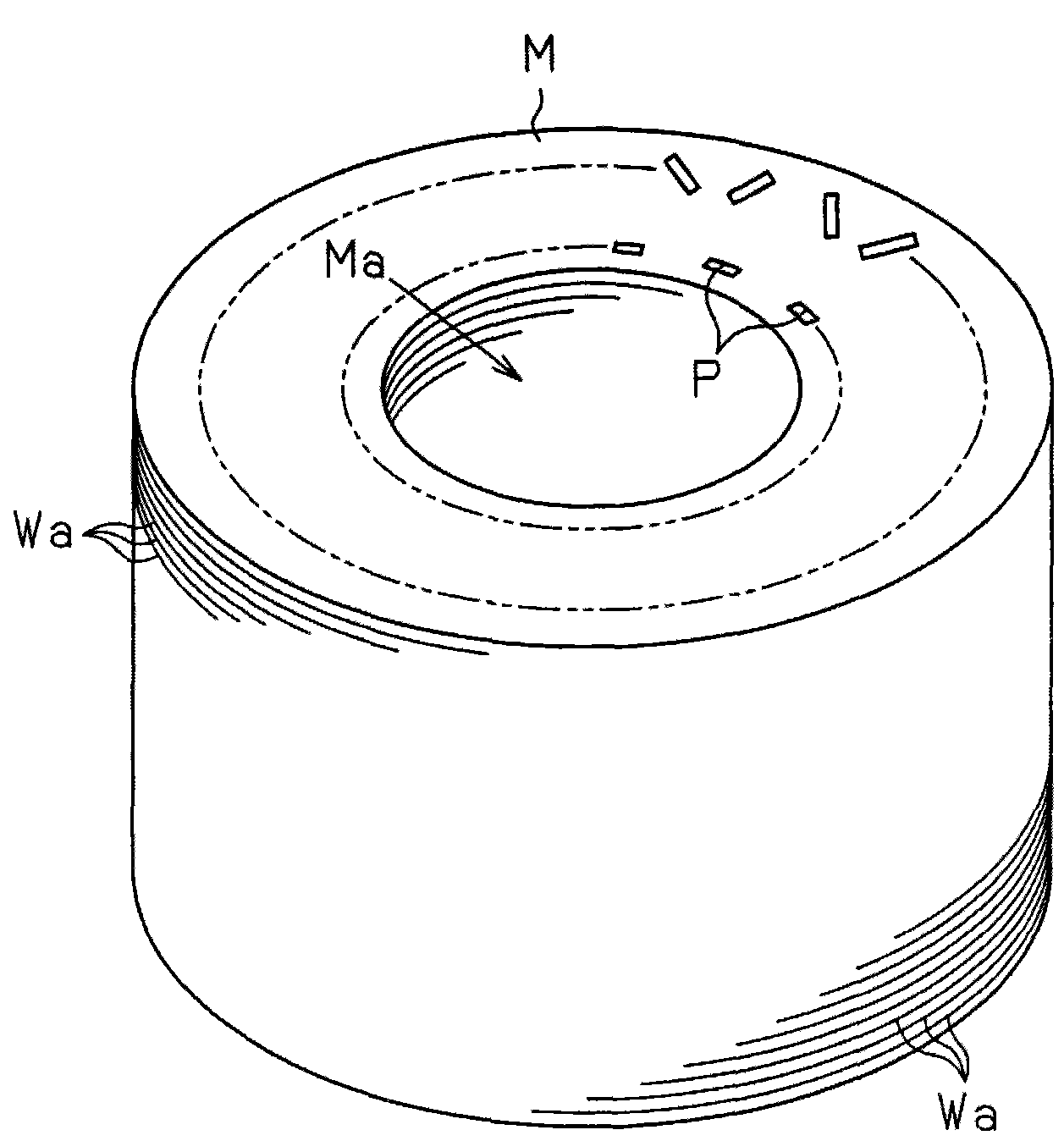
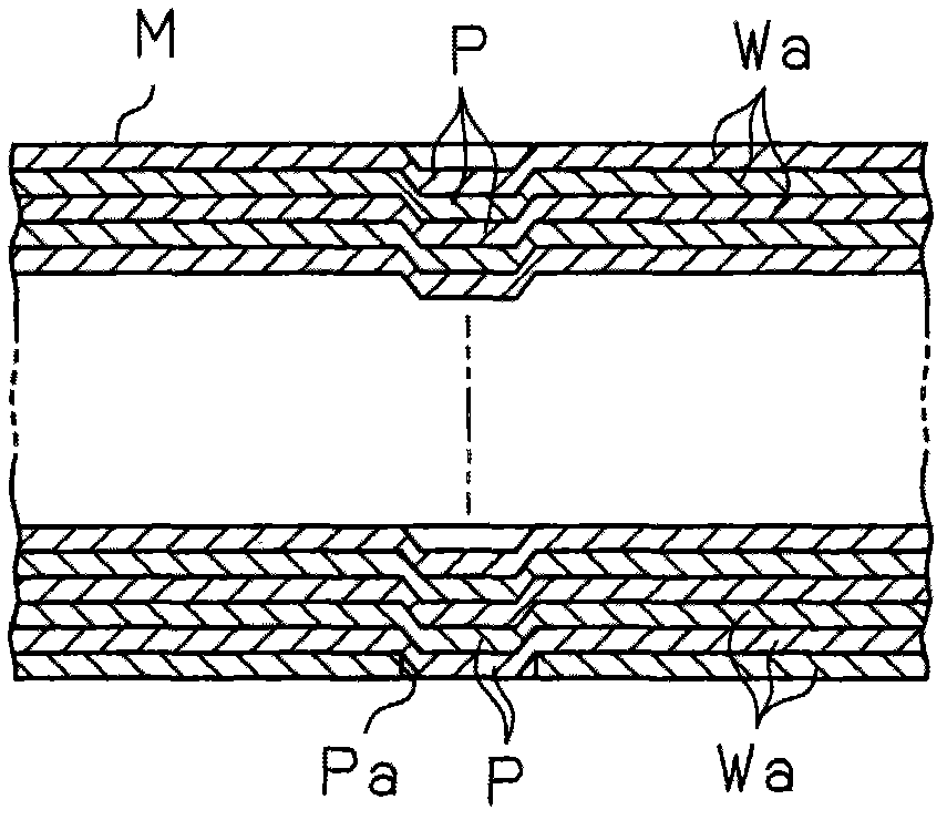
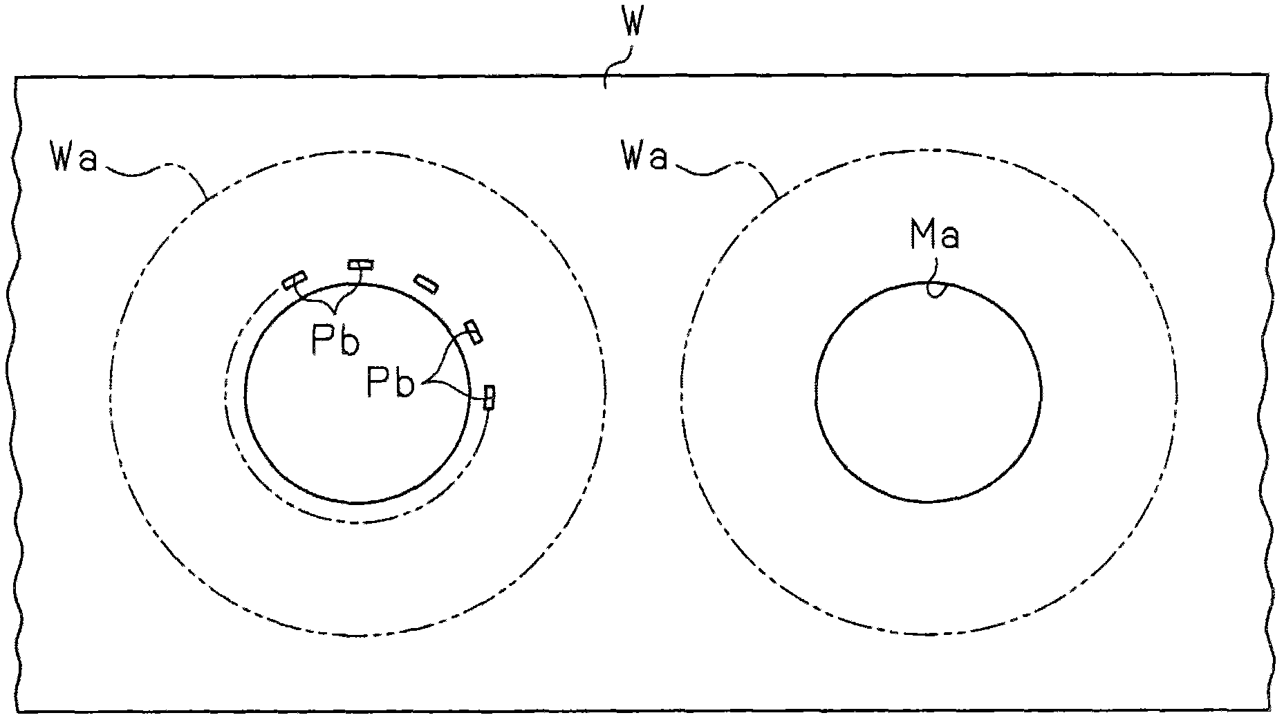
[0029] Such as Figure 4 to Figure 6 As shown in , the press-lamination apparatus includes a workpiece support portion 11 for supporting a workpiece W. The workpiece W is held by the workpiece support portion 11 in one direction ( Figure 4 in the direction of the arrow) to send. Above the workpiece support portion 11, an elevating member 12 serving as an elevating member is provided. The holding member 13 is supported by a spring 14 on the lower surface of the lifting member 12 . The holding member 13 is movable relative to the lifting member 12 in a direction in which the lifting member 12 ascends and descends. The spring 14 applies a downward force to the holding member 13 . When the lifting member 12 descends, the workpiece W is firmly held between the holding member 13 and the workpiece support portion 11 in a state where the workpiece W is placed on the ...
no. 2 approach
[0052] will now refer to Figure 10A and Figure 12DA press-lamination apparatus according to a second embodiment of the present invention is described. In the description of the second embodiment and subsequent embodiments, differences from the first embodiment will be mainly explained.
[0053] The second embodiment is to prevent loss of material and waste of time from occurring when punches 20 are switched after punching a predetermined number (100) of chips has been completed. Such as Figure 9A As shown in , in the first embodiment, after finishing punching a predetermined number of chips in the upstream punching structure 15A, the workpiece W must move through three pitches without punching before the downstream punching structure 15B starts punching again. . Such as Figure 9B As shown in , even if stamping structure 15A starts stamping immediately after stamping structure 15B finishes stamping a predetermined number of chips, there will still be an unprocessed por...
no. 3 approach
[0060] will now refer to Figure 13A to Figure 13D A third embodiment of the present invention will be described.
[0061] In the third embodiment, the selection switching cam 38A of the selection mechanism 37A and the selection switching cam 38B of the selection mechanism 37B are arranged in a direction perpendicular to the direction in which the workpiece W is conveyed, and the selection switching cam 38A, selection switching cam 38A, selection switching cam 38B of the selection mechanism 37A The selection switching cams 38B of the mechanism 37B are connected to each other by a coupling portion 45 . On the lower surface of the selection switching cam 38A corresponding to the upstream punching structure 15A, a convex cam surface 38a, a concave cam surface 38b, a convex cam surface 38a, and a concave cam surface are formed sequentially from the lower side shown in FIG. Surface 38b. On the lower surface of the selection switching cam 38B corresponding to the downstream punchi...
PUM
 Abstract
Description
Claims
Application Information
 - R&D
- Intellectual Property
- Life Sciences
- Materials
- Tech Scout
- Unparalleled Data Quality
- Higher Quality Content
- 60% Fewer Hallucinations
Browse by: Latest US Patents, China's latest patents, Technical Efficacy Thesaurus, Application Domain, Technology Topic, Popular Technical Reports.
© 2025 PatSnap. All rights reserved.Legal|Privacy policy|Modern Slavery Act Transparency Statement|Sitemap|About US| Contact US: help@patsnap.com