System and method for fast parallel cone-beam reconstruction using one or more microprocessor

A wire harness and processing unit technology, applied in material analysis using radiation, material analysis using wave/particle radiation, image data processing, etc., can solve problems such as parallelism not being utilized, and achieve high-precision, high-speed effects

Inactive Publication Date: 2004-04-21
UNIVERSITY OF ROCHESTER
View PDF4 Cites 9 Cited by
  • Summary
  • Abstract
  • Description
  • Claims
  • Application Information

AI Technical Summary

Problems solved by technology

However, such parallelism has not been ex

Method used


Image

  • System and method for fast parallel cone-beam reconstruction using one or more microprocessor
  • System and method for fast parallel cone-beam reconstruction using one or more microprocessor
  • System and method for fast parallel cone-beam reconstruction using one or more microprocessor

Examples


Embodiment Construction

[0027] Preferred embodiments of the present invention will now be explained in detail with reference to the accompanying drawings.

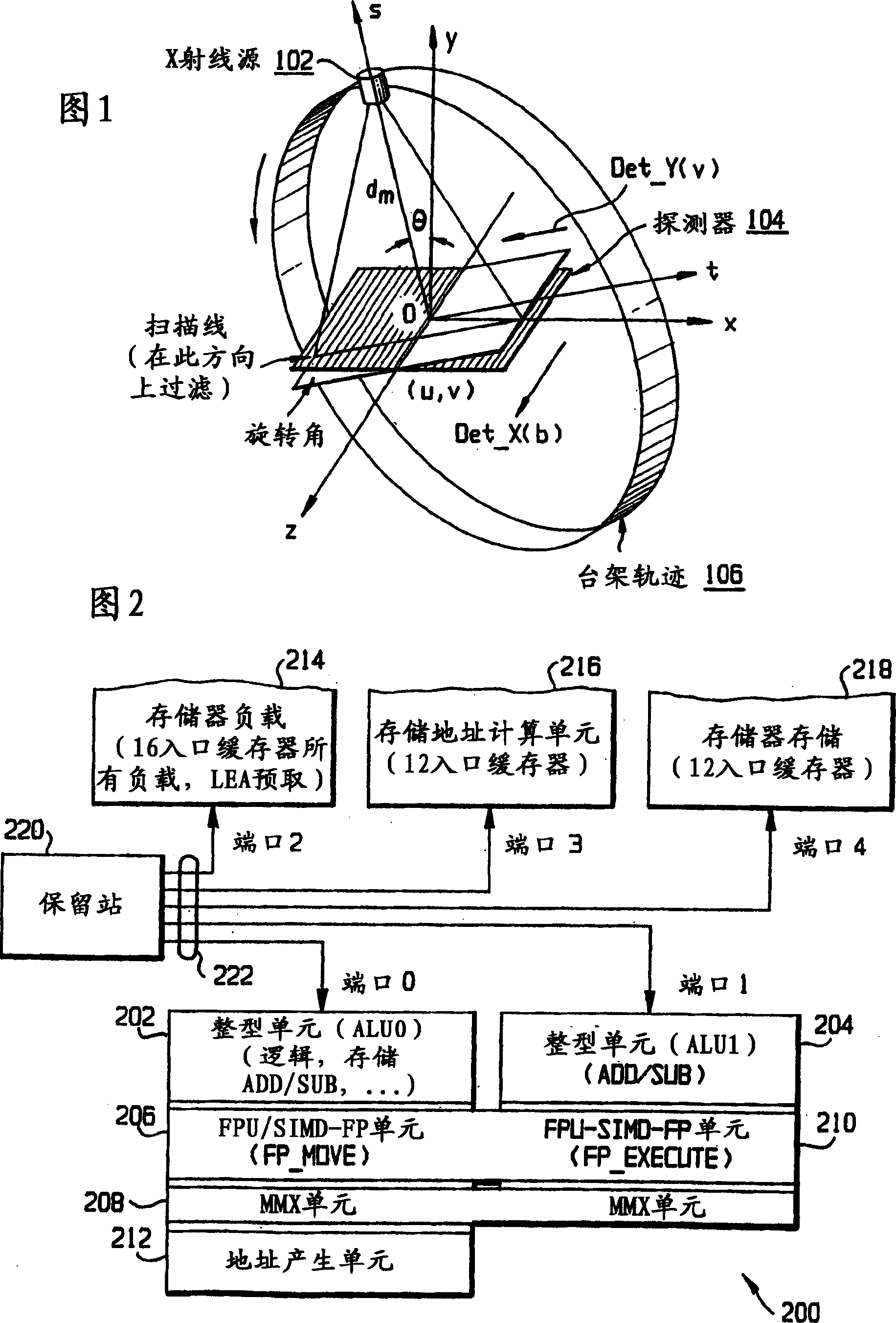
[0028] A preferred embodiment will be described with reference to the coordinate system shown in FIG. 1 . O-XYZ is the world coordinate system. The X-Y-Z axes give the physical coordinates of the voxels used for reconstruction. The Z axis is the axis of rotation. The t-s axis is the rotating gantry X-Y coordinate system. The S axis always passes through the x-ray source and is perpendicular to the detector plane.

[0029] Several research groups have investigated the reconstruction of the cone-beam geometry. The most efficient algorithm in use is that of Feldkamp, ​​L.A., Davis, L.C., and Kress, J.W., "Practical Cone-Beam Algorithm," J Opt. Soc. Am. A 14:(6) 612-619 (1984), and Kak, A.C., and Slaney, M., Principles of Computerized Tomographic Imaging, IEEE Press, 1988. In this algorithm, the projection data is back-projected onto the image ...


PUM


Abstract

Cone-beam reconstruction is performed within a practically acceptable time on a computer having one or more microprocessors. The calculations involved in the reconstruction are divided into calculations to be performed on the MMX, ALU and SSE units of each of the microprocessors. For pure floating-point data, it is preferred to use the MMX unit to adjust the data address and map data and to use the SSE unit to perform the backprojection. The data are partitioned by z-line so that the data to be processed in each stage of the backprojection fit within the L1 cache.

Description

[0001] Statement of Government Interest [0002] This invention was supported in part by NIH Grants 2R01HL48603-05 and 1R41HL59703. The government has certain rights in this invention. technical field [0003] The present invention relates to systems and methods for cone beam reconstruction in medical imaging and the like, and in particular to such systems and methods implemented on one or more microprocessors. The invention can also be used for non-destructive testing, single photon emission tomography and CT-based explosive detection, micro-CT or micro-cone beam volume CT, and the like. Background technique [0004] Cone beam reconstruction has attracted a lot of attention from the medical imaging community. Examples of cone beam reconstructions can be found in commonly assigned U.S. Patents 5,999,587 and 6,075,836 and U.S. Patent Application Nos. 09 / 589,115 and 09 / 640,713, the contents of which are fully incorporated by [0005] used as a reference in this manual. [...

Claims


Application Information

Patent Timeline
IPC IPC(8): A61B6/03G01N23/04G06T11/00
CPCY10S378/901G06T2211/428A61B6/4085G06T11/006G01N23/046A61B6/032G01N2223/419A61B6/583
Inventor 宁若罗
Owner UNIVERSITY OF ROCHESTER
Why Eureka
Try Eureka