Improved setting tool structure of coil cover creep distance

A technology of creepage distance and coil wire, which is applied in the field of motors, can solve the problems of difficult to guarantee the quality of the stator, low shaping efficiency, and difficult to guarantee the creepage distance, etc., and achieve the effect of simple structure, high efficiency and easy realization

Inactive Publication Date: 2013-07-03
ZHEJIANG LINIX MOTOR
View PDF6 Cites 0 Cited by
  • Summary
  • Abstract
  • Description
  • Claims
  • Application Information

AI Technical Summary

Problems solved by technology

Among them, the coil wire package needs to be separated from the end of the stator by a certain distance, that is, the creepage distance. In the prior art, it is difficult to guarantee the creepage distance in the process of shaping the coil package after the winding is completed, the setting efficiency is low, and the quality of the stator is also difficult to guarantee.

Method used


Image

  • Improved setting tool structure of coil cover creep distance
  • Improved setting tool structure of coil cover creep distance
  • Improved setting tool structure of coil cover creep distance

Examples


Embodiment Construction

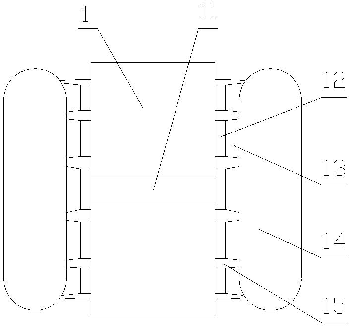
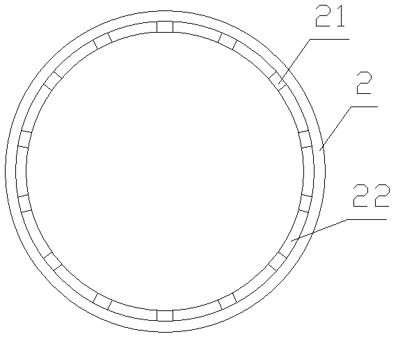
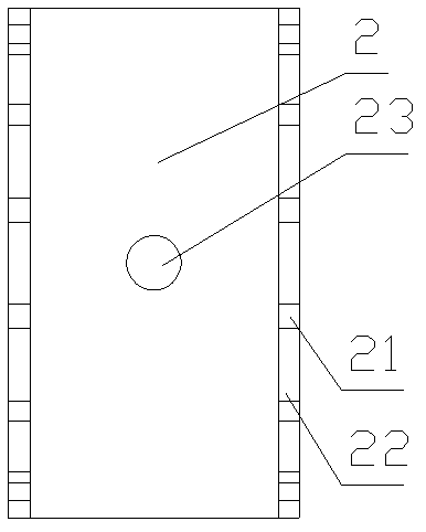
[0021] like Figure 1 to Figure 9 As shown, it is an embodiment of the stereotyped tooling for the creepage distance of the coil wire package of the present invention. The shaped tooling includes a hollow cylindrical mold body 2 set on the outer side wall of the stator 1, and the side walls at both ends of the mold body are in the Several slots 21 are evenly opened in the circumferential direction, and the positions of the slots correspond to the positions of the gaps 15 between the coil slots 12 on the stator. The positioning pieces 3 are inserted in the slots, and the thickness of the positioning pieces is equal to the creepage The setting tool also includes several telescopic claws 6 corresponding to the positioning pieces one by one, and the telescopic claws control clamping or loosening of the positioning piece and control the positioning piece to insert or leave the slot. The shaping tool also includes a gland 4, the gland is in the shape of a barrel, the gland is sleeve...


PUM


Abstract

The invention discloses an improved setting tool structure of a creep distance between coil covers. The setting tool comprises a cylindrical hollow mould body which is sleeved on stator outer side walls, wherein side walls at two ends of the mould body are provided with a plurality of slots respectively at circumference; the slots correspond to gaps among upper coil slots of stators; locating plates are inserted into the slots; and the thickness of the locating plates is equal to the creep distance. The setting tool also comprises a plurality of stretched claws which are in one-to-one correspondence with the locating plates; and the stretched claws are used for clamping or loosening the locating plates and controlling the locating plates to be inserted into or departed from the slots. Themould body which is sleeved on the stators and the locating plates which are inserted into the slots at two ends of the mould body are used for ensuring the creep distance. The improved setting tool structure is simple, is easy to realize and can ensure the creep distance between the coil covers accurately; and in addition, the stretched claws are used for clamping or loosening the locating plates as well as controlling the locating plates to be inserted into or departed from the slots, thus improving the efficiency.

Description

technical field [0001] The invention relates to electric machine technology. Background technique [0002] The coil winding is the main component of the motor stator. The coil group is connected in a certain way at the end to form a stator circuit, and the relative movement with the rotor magnetic flux generates an induced potential to realize mechanical energy-electrical energy conversion. like figure 1 As shown, the coil windings are generally embedded in the coil slots 12 on the inner wall of the stator by wire bundles 13 of the same shape and size, and the wire bundles are stacked one by one on the outside of both ends of the stator to form coil wire packages 14 . Among them, the coil wire package needs to be separated from the end of the stator by a certain distance, that is, the creepage distance. In the prior art, it is difficult to guarantee the creepage distance in the process of shaping the coil package after the winding is completed, the setting efficiency is lo...

Claims


Application Information

Patent Timeline
Patent Type & Authority Patents(China)
IPC IPC(8): H02K15/085
Inventor 朱炎钊
Owner ZHEJIANG LINIX MOTOR
Why Eureka
Try Eureka