Pitch slip ring

A technology of slip rings and conductive rings, which is applied in the direction of current collectors, motor generator connectors, electrical components, etc., and can solve problems such as creepage, reduced creepage distance between brush wire and insulating ring, and unstable contact. Achieve good guiding and limiting effects, improve signal transmission quality, and increase the conductive contact area

Active Publication Date: 2017-12-26
大连宜顺机电有限公司
View PDF6 Cites 0 Cited by
  • Summary
  • Abstract
  • Description
  • Claims
  • Application Information

AI Technical Summary

Problems solved by technology

like figure 1 and figure 2 As shown, the contact between the existing conductive ring and the brush is unstable, and under severe vibration conditions, it is easy to cause the contact between the brush wire and the insulating ring, thereby reducing the creepage distance and easily causing creepage

Method used


Image

  • Pitch slip ring
  • Pitch slip ring
  • Pitch slip ring

Examples


Embodiment Construction

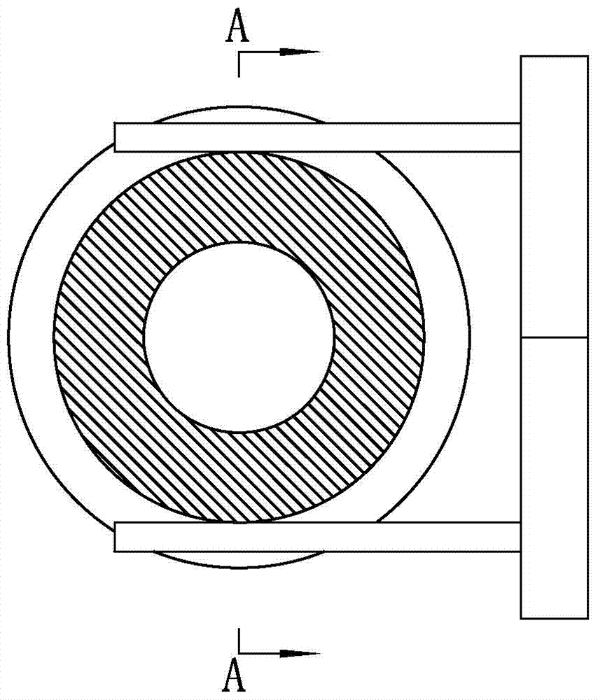
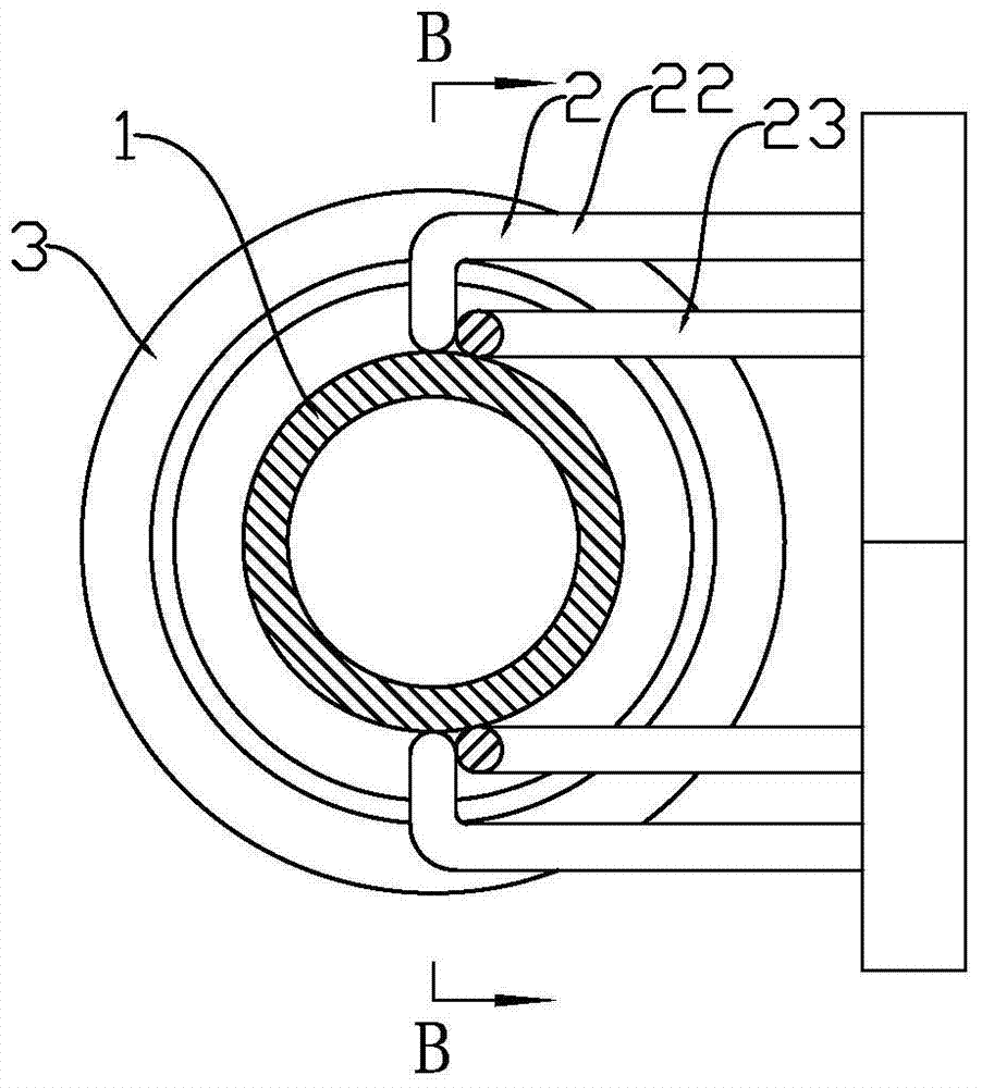
[0016] Such as image 3 and Figure 4 As shown, a pitch slip ring includes a conductive ring 1 and a conductive brush wire 2, an insulating ring 3 is provided on both sides of the conductive ring 1, and a surrounding groove 11 is provided on the outer side of the conductive ring. The end of the brush filament 2 is provided with a brush head 21 that cooperates with the groove 11. The brush head 21 is in line contact or surface contact with the bottom of the groove 11, and the conductive contact area is increased. The original point contact becomes Line contact or surface contact reduces contact resistance and improves signal transmission quality, and the arrangement of the groove 11 prevents the conductive brush wire 2 from contacting the insulating ring 3 and prevents creepage.

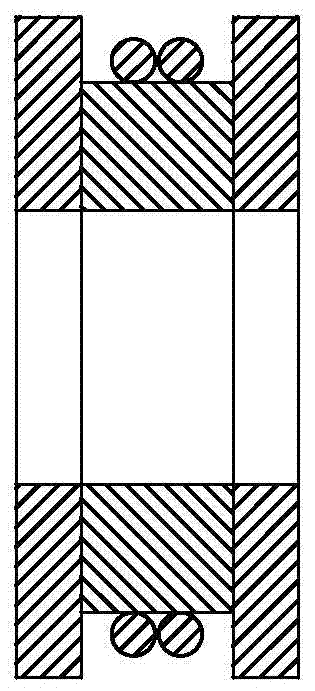
[0017] The brush head 21 is a T-shaped brush head, and the inner side of the groove 11 is provided with a limiting protrusion 12 that can limit the T-shaped brush head in the groove 11. Next, the br...


PUM


Abstract

The invention discloses a variable-pitch slip ring. The variable-pitch slip ring comprises a conductive ring and a conductive brush wire, wherein insulating rings are arranged on the two sides of the conductive ring; a groove is formed, surrounding the periphery, in the outer side of the conducive ring; a brush head matched with the groove is arranged at the end part of the conductive brush wire; and the brush head and the bottom of the groove are in line contact or surface contact. According to the variable-pitch slip ring, the width of the conductive ring is kept the same, and the conductive contact area is enlarged by changing the original point contact into line contact or surface contact, so that the contact resistance is reduced and the signal transmission quality is improved; a T-shaped slot structure has a good guide and limiting function, so that the conductive brush wire can be well positioned in the T-shaped slot in rotation without being in contact with the insulating rings; and therefore, an electrical creep distance is well ensured, and stable rotation contact between the brush wire and the conductive ring is ensured as well.

Description

technical field [0001] The invention relates to a conductive slip ring, in particular to a pitch-variable slip ring. Background technique [0002] The main function of the pitch slip ring of the wind turbine is to be responsible for the conductive transmission of the pitch motor power channel in the rotating hub of the wind turbine and the transmission of control signals and communication signals of other electrical devices. The hub rotates with the blades and other factors cause vibration. Relatively large, so that the vibration resistance requirements for electrical conduction and signal transmission are higher. If power failure or serious data packet loss occurs during signal transmission, the entire unit will eventually be shut down. Therefore, the requirements for signal transmission quality of the pitch slip ring are relatively high. By studying the rotating contact conductive contact structure, the contact conduction resistance to vibration is improved, and the quali...

Claims


Application Information

Patent Timeline
Patent Type & Authority Patents(China)
IPC IPC(8): H01R39/10H01R39/24
CPCH01R39/10H01R39/24H01R2201/10
Inventor 张令威唐宇飞王勇曾庆刚孔凡杰景春辉王超李杰
Owner 大连宜顺机电有限公司
Why Eureka
Try Eureka