Socket

A socket and socket panel technology, applied in the direction of contact parts, fixed/insulated contact members, electrical components, etc., can solve the problems of increasing the contact area, and the deformation of the copper sheet cannot be recovered, so as to increase the conductive contact area and prevent extrusion deformation. , the effect of reducing heat

Pending Publication Date: 2020-09-11
苏茂均
View PDF0 Cites 0 Cited by
  • Summary
  • Abstract
  • Description
  • Claims
  • Application Information

AI Technical Summary

Problems solved by technology

[0004] In order to solve the above-mentioned problems, the contact plate in plane contact is matched with the spring holding mechanism, and the contact plate is translated as a whole through the spring support mechanism, and the conductive contact plane of the contact plate is in contact with the plug, increasing the contact area and avoiding electric shock at the same time. The problem that the traditional copper sheet deformation caused by sheet deformation cannot be recovered

Method used


Image

  • Socket
  • Socket
  • Socket

Examples


Embodiment 1

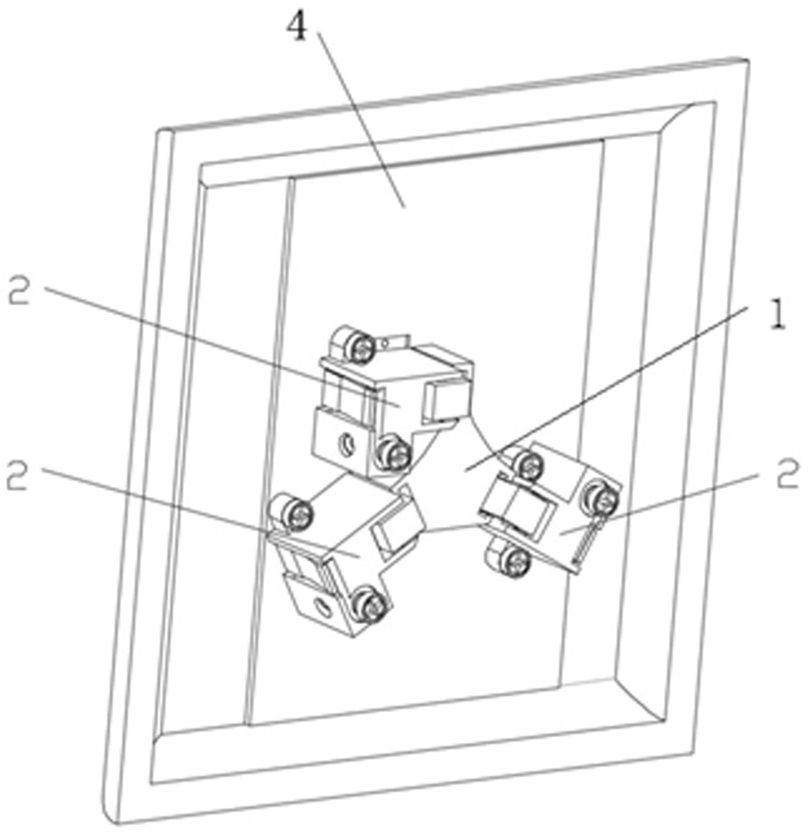
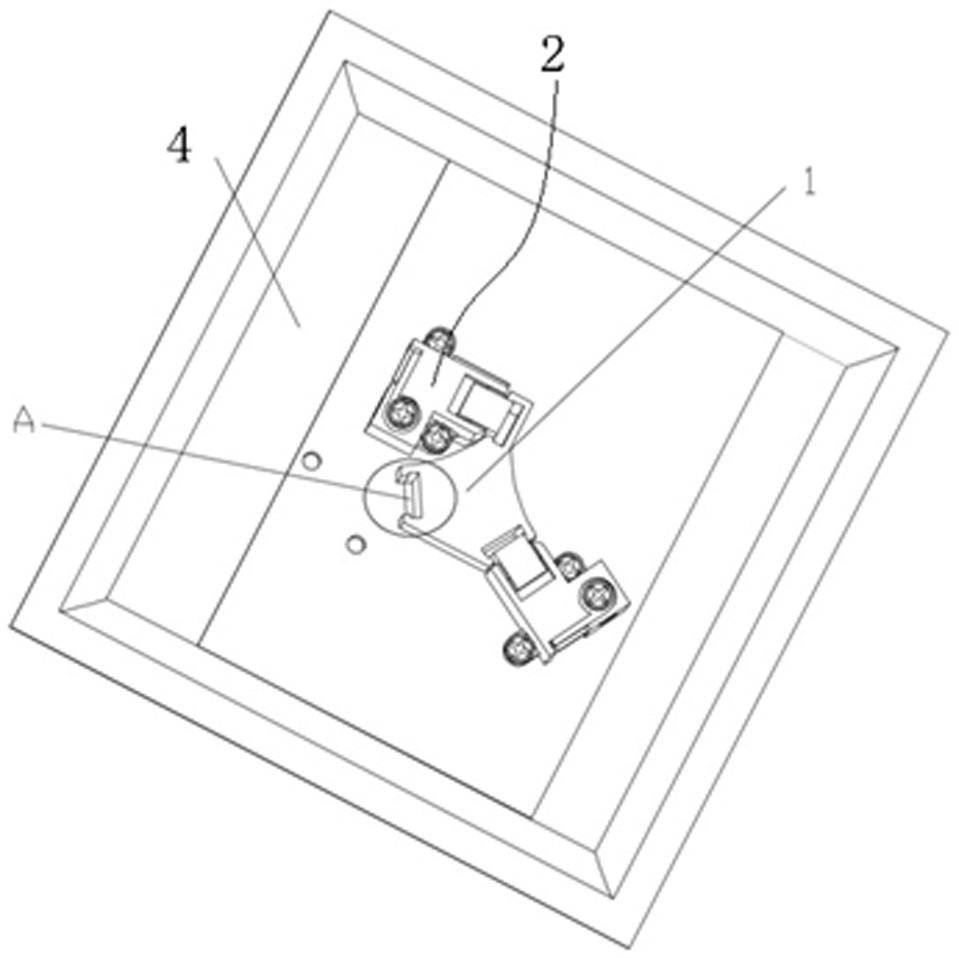
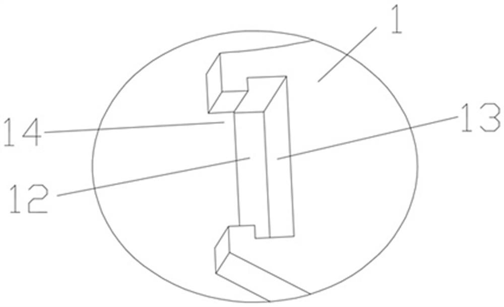
[0038] Example 1, see Figure 1-Figure 6 ,as well as Figure 12-13 , a socket provided in this embodiment is provided with a socket panel 4 , and the socket panel 4 is provided with a latch 31 and a fixing frame 1 .

[0039] The fixed frame 1 of the latch 31 is provided with a latch groove 12 adapted to fit the plug 3 latch 31, and one side of the latch groove 12 is provided with a notch 14, which facilitates the movement of the connecting sheet 21 of the electrical connection system 2 .

[0040] The fixing frame 1 of the bolt 31 is arranged inside the socket panel 4 , and the bolt groove 12 extends toward the outside of the socket panel 4 and intersects with the outside of the socket panel 4 to form a bolt hole. The pin holes can be provided with two pin holes or three pin holes, which are adapted to two-pin plugs 3 or three-pin plugs and four-pin plugs 3 respectively.

[0041] The inner side of the socket is provided with an electrical connection system 2, the electrical ...

Embodiment 2

[0049] Example 2, see Figure 7-Figure 13 , a socket provided in this embodiment, embodiment 2 is basically the same as embodiment 1, the difference is that the bolt 31 fixing frame 1 and the mounting base 23 are connected into one structure.

[0050] The latch 31 fixing frame 1 is provided with a latch groove 12 adapted to match the latch 31 of the plug 3 . The plug groove 12 and the mounting seat 23 are connected as a whole to form a rectangular cavity. One side of the rectangular cavity is a mounting groove for the connecting plate, and the conductive contact plane 211 of the connecting plate 21 is embedded in the slotting groove. The distance between the conductive contact plane 211 of the electric piece 21 and the side wall of the slot is smaller than the thickness or diameter of the pin 31 of the plug 3 .

[0051] The mounting base 23 is provided with an external power access hole 28 , and the external power access hole 28 communicates with the external power connection...


PUM


Abstract

The invention discloses a socket, which is provided with a socket panel and an electric connection system. The socket panel is provided with a bolt fixing frame. The electric connection system is provided with a mounting seat, a power connection sheet and a spring jacking mechanism, and the mounting seat is provided with a power connection sheet mounting groove and a spring groove. Through arranging the bolt fixing frame, when the plug and the plug pin are inserted into the socket, the plug pin is inserted into the plug pin fixing frame, the plug pin fixing frame can fix the plug pin, and whenthe plug pin makes contact with the conductive contact plane of the power connection piece, under the action of the jacking spring and the plug pin fixing frame, tight combination of the plug pin andthe conductive contact plane can be guaranteed, and the plug pin can be prevented from being bent or deformed. The conductive contact planes of the power connection sheets are in surface-to-surface contact with the conductive sheets of the plug, so that the conductive contact area is increased, and the heat productivity during electrification is reduced. Because the power connection sheet moves left and right under the acting force of the spring jacking mechanism, the power connection sheet does not deform in the moving process.

Description

technical field [0001] The invention relates to the technical field of electrical sockets, in particular to sockets. Background technique [0002] Existing power plug and socket, after the plug is inserted into the socket, only the contact effect of the blade of the plug and the clip of the socket plays a role in connection, and this contact effect also plays an electrification effect simultaneously. This kind of connection is very loose, and the electrical appliances or electric tools connected with the plug often move during use, so it is possible to pull the plug and make the plug and the socket loose, which affects the work. In addition, the clips of sockets are now made by bending a piece of copper. The clamping effect on the plug inserts only depends on the elasticity of the copper itself, and the elasticity of the copper is really limited, and there is metal fatigue. Especially after being inserted by a thick insert or a round plunger, there is often a situation that...

Claims


Application Information

Patent Timeline
Patent Type & Authority Applications(China)
IPC IPC(8): H01R13/187H01R13/10H01R13/40
CPCH01R13/10H01R13/187H01R13/40
Inventor 苏茂均
Owner 苏茂均
Why Eureka
Try Eureka