Transformer wiring device

A wiring device and transformer technology, applied in the direction of transformer/coil connector, transformer/inductor coil/winding/connection, connection, etc., can solve the problems of unreliable connection, narrow space, inconvenient loading and unloading, etc., and achieve uniform force, The effect of large conductive contact area and reliable connection

Pending Publication Date: 2019-12-24
GUANGZHOU PANYU CABLE WORKS
View PDF0 Cites 1 Cited by
  • Summary
  • Abstract
  • Description
  • Claims
  • Application Information

AI Technical Summary

Problems solved by technology

The fastening mechanism of the traditional wiring device usually uses threaded connection to directly thread the wiring device to the transformer terminal stud. This method of purely relying on the threaded connection is easy to loosen and cause the connection to be unreliable, and when loading and unloading It is necessary to rotate the entire wiring device to make it threaded with the terminal studs, so the external wires must be removed when loading and unloading. In addition, rotating the entire wiring device also requires a large space, and the upper surface of the transformer is generally arranged with multiple terminal studs , the space is relatively narrow, and it takes a lot of space to rotate the entire wiring device, so it is extremely inconvenient to install and disassemble

Method used


Image

  • Transformer wiring device
  • Transformer wiring device
  • Transformer wiring device

Examples


Embodiment Construction

[0024] A transformer wiring device of the present invention will be further described below in conjunction with the accompanying drawings:

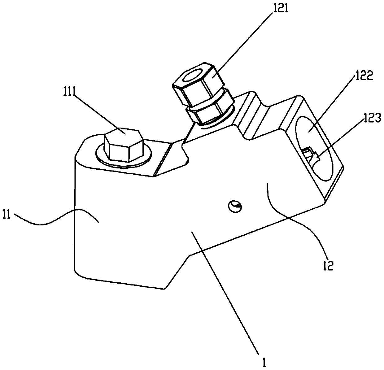
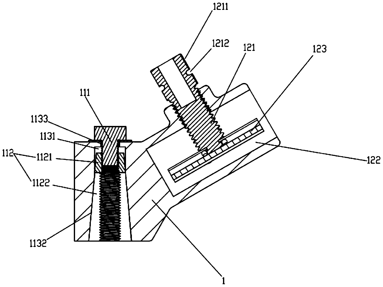
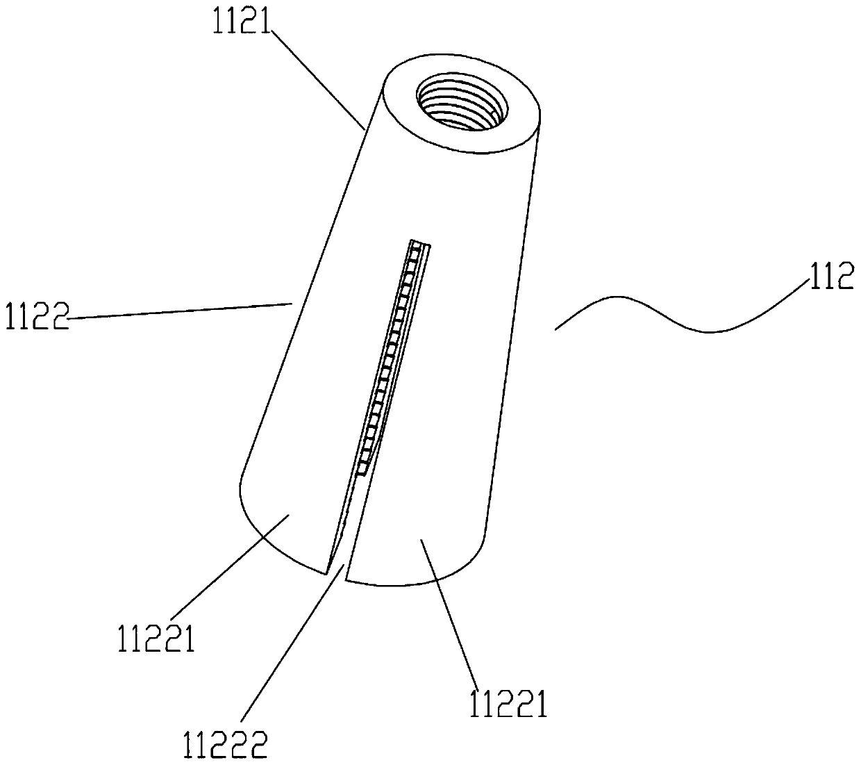
[0025] Such as Figure 1-6 As shown, a transformer wiring device includes a metal wiring device body 1. The wiring device body 1 is provided with a fastening mechanism 11 for fixedly connecting the transformer terminal stud 2 and a wiring mechanism 12 for fixedly connecting external wires. The mechanism 11 includes a tension bolt 111, a metal crimping sleeve 112, and a tightening hole 113 provided on the wiring device body 1. The crimping sleeve 112 is coaxially built into the tightening hole 113, and the tightening hole 113 is divided into upper accommodating The hole 1131 and the lower tapered constriction hole 1132, the top center of the accommodating hole 1131 is provided with a through hole 1133, the bottom of the conical constriction hole 1132 runs through the bottom of the wiring device body 1, and the crimping sleeve 112 is an int...


PUM


Abstract

The invention relates to the technical field of power tools and particularly relates to a transformer wiring device. The transformer wiring device comprises a wiring device body provided with a fastening mechanism and a wiring mechanism. The fastening mechanism comprises a tension bolt, a conical crimping sleeve and a conical tightening hole formed in the wiring device body; the crimping sleeve iscoaxially arranged in the tightening hole; the conical crimping sleeve is attached to the conical tightening hole, and both small-diameter ends face upwards; the conical side wall of the lower part of the crimping sleeve is enclosed by at least two elastic crimping sheets; an inner hole of the crimping sleeve is a screw hole; one end of the tension bolt is hung outside the wiring device body through a screw head, and the other end is in threaded connection with the upper part of the crimping sleeve; and the lower part of the crimping sleeve is in threaded connection with the transformer wiring stud. The transformer wiring device provided by the invention is firmly connected with the transformer wiring stud, is convenient to assemble and disassemble, and occupies small space during assembly and disassembly.

Description

technical field [0001] The invention relates to the technical field of power tools, in particular to a transformer wiring device. Background technique [0002] The transformer wiring device is used to fix and electrically connect the external wires to the transformer wiring studs, and generally includes a fastening mechanism for fixedly connecting the transformer wiring studs and a wiring mechanism for fixing the connecting wires. The fastening mechanism of the traditional wiring device usually uses threaded connection to directly thread the wiring device to the transformer terminal stud. This method of purely relying on the threaded connection is easy to loosen and cause the connection to be unreliable, and when loading and unloading It is necessary to rotate the entire wiring device to make it threaded with the terminal studs, so the external wires must be removed when loading and unloading. In addition, rotating the entire wiring device also requires a large space, and th...

Claims


Application Information

Patent Timeline
Patent Type & Authority Applications(China)
IPC IPC(8): H01R11/01H01R11/05H01R4/50H01R4/36H01F27/28
CPCH01F27/28H01R4/366H01R4/5016H01R11/01H01R11/05H01R2201/22
Inventor 胡超强徐加健林杉杉尤占山王骞能胡玉莹陈雪儿徐秋燕刘金勇梁健芬魏鹏飞
Owner GUANGZHOU PANYU CABLE WORKS
Why Eureka
Try Eureka