Low-torque ripple permanent magnet flux-switching motor

A permanent magnet switch, torque ripple technology, applied in the direction of magnetic circuit rotating parts, electrical components, electromechanical devices, etc., can solve the problems of large motor positioning torque, large motor torque ripple, limited application, etc., to reduce The effect of positioning torque and torque ripple, low environmental requirements and good field weakening performance

Inactive Publication Date: 2011-11-16
SHANGHAI DIANJI UNIV
View PDF3 Cites 13 Cited by
  • Summary
  • Abstract
  • Description
  • Claims
  • Application Information

AI Technical Summary

Problems solved by technology

[0005] However, the electromagnetic torque of the permanent magnet switch flux linkage motor is mainly generated by the permanent magnet, the reluctance torque is relatively small, and the positioning torque of the motor is relatively large, resulting in relatively large torque ripple of the motor, and the resulting vibration and noise are biased. Big
[0006] It is known from the above that the permanent magnet switch flux linkage motor in the prior art has a large positioning torque and prominent torque ripple, which limits its application in the servo field and other occasions that require high torque ripple.

Method used


Image

  • Low-torque ripple permanent magnet flux-switching motor
  • Low-torque ripple permanent magnet flux-switching motor
  • Low-torque ripple permanent magnet flux-switching motor

Examples


Embodiment Construction

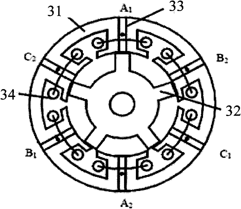
[0028] See Figure 5(a). A low-torque pulsation permanent magnet switch flux linkage motor 10 according to the present invention is composed of two permanent magnet switch flux linkage motors 8 and 9 with identical structures, and the two parts share a housing (not shown) and a rotating shaft 4. Place it left and right; when the two teeth of the stator core 6 are aligned, the two teeth of the rotor core 3 are staggered by an electrical angle of 180 / P degrees. When the two teeth of the rotor core 3 are aligned, the two teeth of the stator core 6 The segment teeth are staggered by 180 / P degree electrical angle, and P is the number of phases.

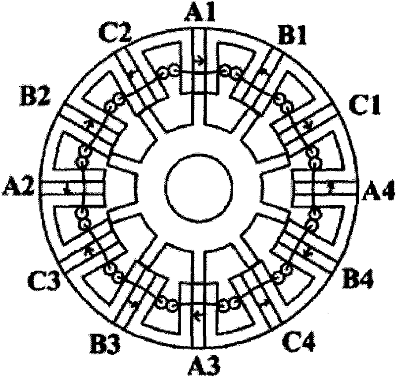
[0029] Continue to refer to accompanying drawing 5 (a). The structures of the permanent magnet switch flux linkage motors 8 and 9 are exactly the same, the stator is composed of tangentially magnetized permanent magnets 1 and U-shaped stator cores 6 arranged in sequence, the N poles and S poles of the permanent magnets 1 are arranged alter...


PUM


Abstract

The invention provides a low-torque ripple permanent magnet flux-switching motor, which is formed by combining two permanent magnet flux-switching motors with a completely identical structure. The two permanent magnet flux-switching motors share a shell and a rotating shaft, and are arranged on a left side and a right side. Two sections of teeth of a rotor core are staggered by an electrical angle of 180 / P degrees under the condition of aligning the two sections of teeth of a stator core, and the two sections of teeth of the stator core are staggered by the electrical angle of 180 / P degrees under the condition of aligning the two sections of teeth of the rotor core, wherein P is a phase number. The low-torque ripple permanent magnet flux-switching motor has the advantages of high efficiency, power density, reliability and back electromotive force waveform sinusoidal properties, vast application prospect and the like, and is easy to control.

Description

technical field [0001] The invention relates to a permanent magnet switch flux linkage motor, in particular to a low torque pulsation permanent magnet switch flux linkage motor. Background technique [0002] The permanent magnet flux-switching motor (PMFSM) with permanent magnets embedded in the stator teeth was first proposed by scholars Rauch and Johnson in 1955. Its structure is as follows: figure 1 As shown, there was little research on this kind of motor for a long time afterwards. With the development of permanent magnet materials, scholars such as Hoang refocused their research on PMFSM in 1997, and then some people proposed a hybrid excitation switching flux linkage motor, such as figure 2 shown. In recent years, domestic scholars have also begun to study permanent magnet switch flux linkage motors. image 3 Shown is a cross-sectional view of a 24V, 450W, 1500r / min three-phase 6 / 5 pole structure permanent magnet switch flux linkage motor developed by Zhejiang Uni...

Claims


Application Information

Patent Timeline
Patent Type & Authority Applications(China)
IPC IPC(8): H02K29/00H02K1/17H02K1/14H02K3/04H02K1/22
Inventor 袁龙生赵朝会李键陈垒项峰
Owner SHANGHAI DIANJI UNIV
Why Eureka
Try Eureka