
Light source unit, illuminating device, display device and television receiver

A technology for a light source unit and a display device, which is applied in the fields of lighting devices, display devices, television receivers, and light source units, can solve the problems of light guide configuration deviation, display quality degradation, and light guide width, etc., so as to prevent the display quality from deteriorating. Effect

Inactive Publication Date: 2011-11-16
SHARP KK
View PDF1 Cites 1 Cited by
  • Summary
  • Abstract
  • Description
  • Claims
  • Application Information

AI Technical Summary

Problems solved by technology

However, it is difficult to arrange all the light guides at regular intervals, so there may be deviations in the arrangement of the light guides, resulting in wider or narrower intervals between the light guides than the specified interval.
Here, since the gap between the light guides does not emit light, when the gap becomes larger, dark lines may be displayed along the boundaries of multiple light guides arranged in parallel, resulting in a decrease in display quality.

Method used


Image

  • Light source unit, illuminating device, display device and television receiver
  • Light source unit, illuminating device, display device and television receiver
  • Light source unit, illuminating device, display device and television receiver

Examples


Embodiment approach 1

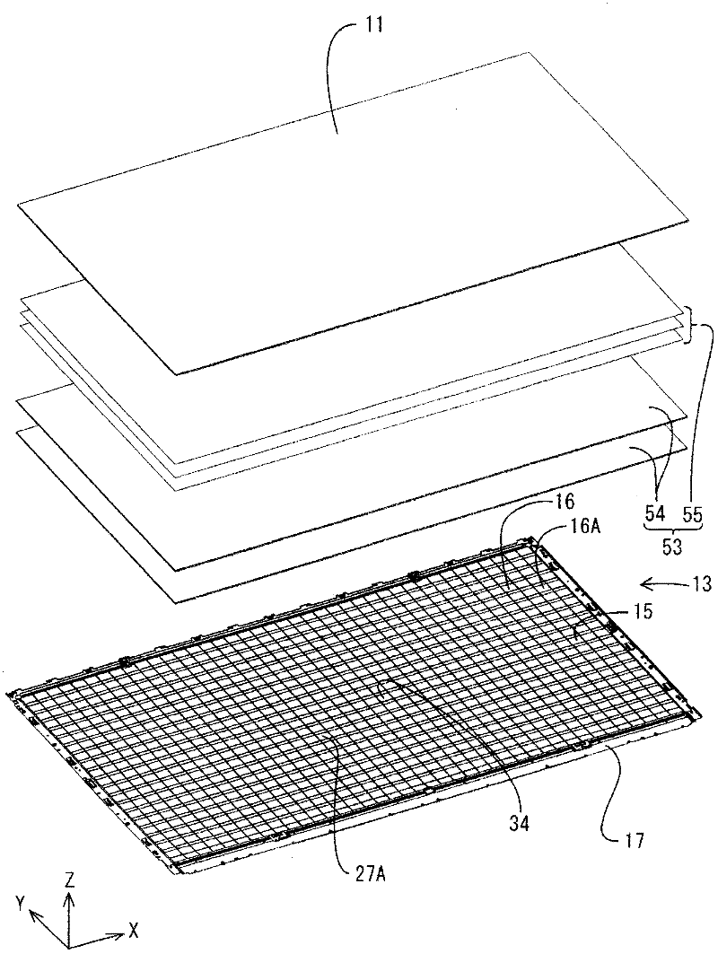
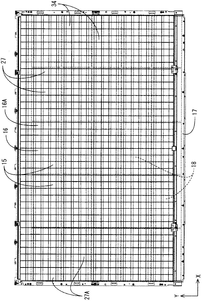
[0057] Below, refer to Figure 1 to Figure 9 Embodiment 1 of the present invention will be described.

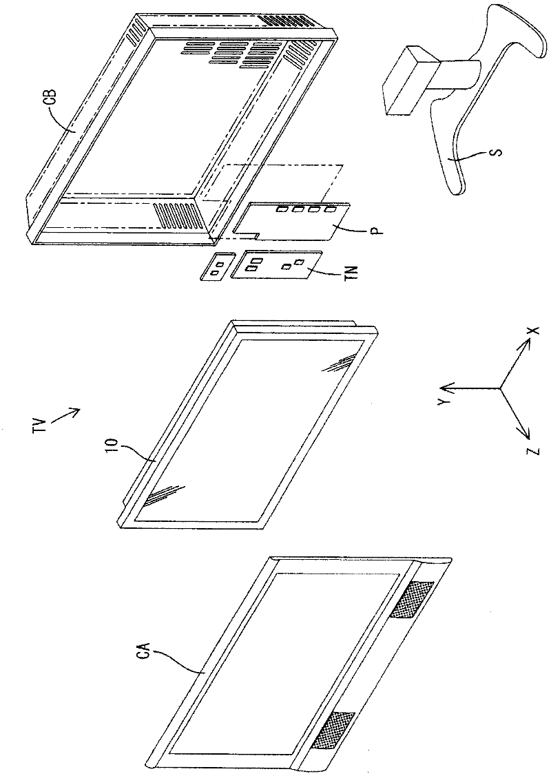
[0058] In this embodiment, a television receiver TV including a liquid crystal display device 10 (display device) is exemplified. Such as figure 1 As shown, the television receiving device TV includes: a liquid crystal display device 10; casings CA and CB for accommodating the liquid crystal display device 10 in a manner sandwiched from the front and back; a power supply P; a tuner TN for receiving TV broadcasts, etc.; and a pedestal S. The liquid crystal display device 10 is housed in the cabinets CA, CB in a vertical orientation with the display surface facing a substantially vertical direction. Below, with figure 1 Each component will be described with the lower left side (the front side and the display side of the television receiver TV) as the front direction and the upper right side as the rear direction. In addition, the X-axis direction shown in the figure repre...

Embodiment approach 2

[0101] Next, refer to Figure 10 A liquid crystal display device 70 according to Embodiment 2 of the present invention will be described.

[0102] The difference between the liquid crystal display device 70 of the present embodiment and the first embodiment lies in the different shape of the extension portion 71 . In addition, the same code|symbol is attached|subjected to the same structure as Embodiment 1, and repeated description is abbreviate|omitted.

[0103] The liquid crystal display device 70 in this embodiment includes, as in the first embodiment, a liquid crystal panel 11 capable of displaying images, and a backlight unit 13 that irradiates light toward the liquid crystal panel 11 . Also, like Embodiment 1, backlight unit 13 includes: light source unit 16 in which a plurality of LEDs 14 and light guide plate 15 are arranged in a planar arrangement; and optical member 53 arranged on the front side of light source unit 16 .

[0104] Furthermore, as in Embodiment 1, a ...


PUM


Abstract

Provided are a light source unit wherein display qualities are prevented from deteriorating, an illuminating device, a display device and a television receiver. In the light source unit, a plurality of light guide bodies (27) are arranged side by side in a first direction and a second direction which substantially orthogonally intersects the first direction. Each of the light guide bodies (27) is flatly shaped, has a light outputting section (27A) which outputs inputted light, and a light guide section (27B) which guides the inputted light to the light outputting section (27A). On the both facing side end sections of the light guide bodies (27) adjacent to each other in the second direction, extending sections (40) which slope and extend in the front-rear direction are provided. The light guide bodies (27) are arranged such that on the front side of the light guide section (27B) of one light guide body (27), a light outputting section (27A) of other light guide body (27) is placed in the first direction, and in the second direction, the extending sections (40) are placed one over another in the front-rear direction.

Description

technical field [0001] The present invention relates to a light source unit, an illuminating device, a display device and a television receiving device. Background technique [0002] As an illuminating device for a display panel in the prior art, there is known an illuminating device having a light source unit in which a plurality of light sources and a plurality of light guides ( For example, Patent Document 1). A lighting device having such a light source unit has the advantage of being able to illuminate the entire display panel with high luminance compared to a side-type lighting device in which light enters from the side of a single light guide plate, for example. [0003] Patent Document 1: Japanese Unexamined Patent Application Publication No. 2004-265635 [0004] (The problem to be solved by the invention) [0005] However, in lighting devices including the light source unit described above, in order to allow thermal expansion and contraction of the light guides, ...

Claims


Application Information

Patent Timeline
Patent Type & Authority Applications(China)
IPC IPC(8): F21S2/00G02F1/13357F21Y101/02
CPCG02B6/0055G02B6/0088G02B6/0021G02F1/133606G02B6/008G02F1/133611
Inventor 吉川贵博
Owner SHARP KK
Learn More