Speaker unit and portable information terminal
A loudspeaker and magnetic yoke technology, applied in the field of loudspeaker units and portable information terminals, can solve the problems of difficulty in increasing the sound pressure of the loudspeaker unit and the limitation of the enlargement of the magnetic body, and achieve the effects of increasing the sound pressure, realizing miniaturization, and improving the magnetic efficiency.
- Summary
- Abstract
- Description
- Claims
- Application Information
AI Technical Summary
Problems solved by technology
Method used
Image

Examples
Embodiment approach 1
[0030] First, the structure of the speaker unit of this embodiment will be described.
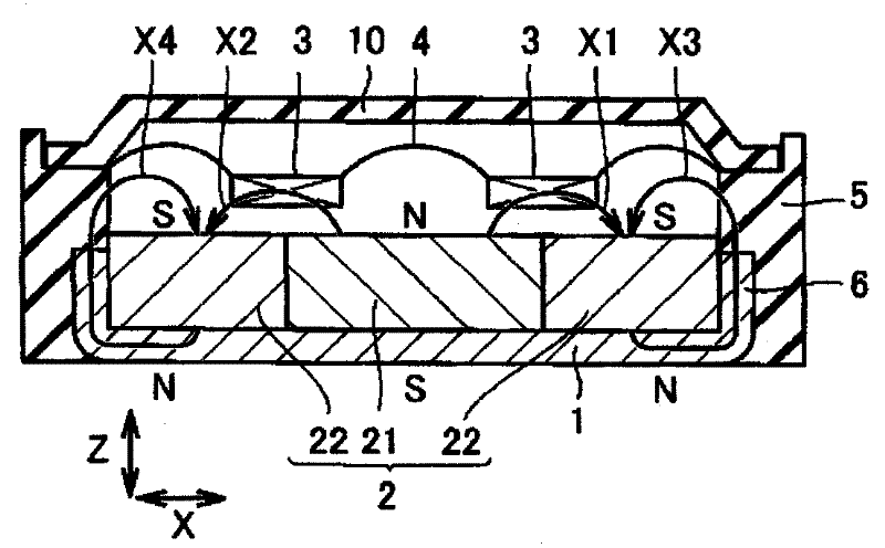
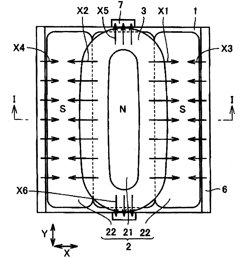
[0031] figure 1 It is a schematic cross-sectional view showing the structure of the speaker unit in Embodiment 1 of the present invention. figure 2 yes figure 1 A simplified top view of the loudspeaker unit shown. It should be noted that, in figure 2 In FIG. 2 , the vibration plate and the frame cover are not shown for easy observation. along figure 2 A brief cross-sectional view of the I-I line is figure 1 .
[0032] refer to figure 1 and figure 2 , The speaker unit of this embodiment mainly includes a yoke 1 , a magnet member 2 , a coil 3 , a diaphragm 4 , a frame 5 , a frame cover 10 , and a protrusion 6 . Such as figure 2 As shown, the yoke 1 has a rectangular shape in plan view. The magnet member 2 is arranged in contact with the yoke 1 . The magnet member 2 is magnetized in the order of S pole, N pole, and S pole on the upper surface along the X direction (one directi...
Embodiment approach 2
[0063] First, the structure of the speaker unit of this embodiment will be described.
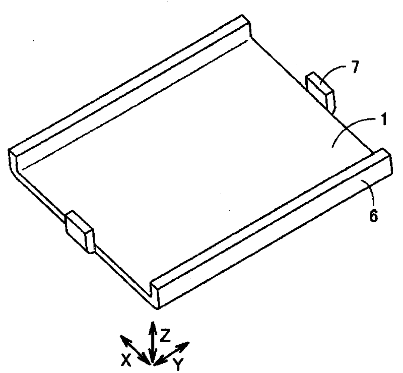
[0064] Figure 12 It is a schematic perspective view of a yoke used in the speaker unit according to Embodiment 2 of the present invention. refer to Figure 12 Compared with Embodiment 1, the main difference of the speaker unit of this embodiment is that the engagement protrusion 7 of the yoke 1 has the bent portion 8 bent outward.
[0065] Figure 13 It is a schematic perspective view of the yoke and the magnet component of this embodiment. refer to Figure 13 The magnet member 2 composed of a plurality of magnetic bodies including a first magnetic body whose upper surface is magnetized to an N pole and a second magnetic body whose upper surface is magnetized to an S pole is arranged on the yoke 1 .
[0066] Figure 14 It is a schematic perspective view of the yoke and frame of embodiment. Figure 15 is along Figure 14 A brief sectional view of line XV-XV. refer to Figure 14 an...
Embodiment approach 3
[0073] First, the structure of the speaker unit of this embodiment will be described.
[0074] Figure 17 It is a schematic sectional view showing the structure of the speaker unit according to Embodiment 3 of the present invention. Figure 18 yes Figure 17 A simplified top view of the loudspeaker unit shown. It should be noted that, in Figure 18 In FIG. 2 , the vibration plate and the frame cover are not shown for easy observation. along Figure 18 A brief sectional view of line XVII-XVII is Figure 17 .
[0075] refer to Figure 17 and Figure 18 , compared with Embodiment 2, the main difference of the speaker unit of this embodiment is that the convex portion 6 of the yoke 1 has a cutout portion 9 in the center. Both end portions 22 of the magnet member 2 are not in contact with the convex portion 6 at portions adjacent to the notch portion 9 .
[0076] Figure 19 It is a schematic perspective view of the yoke of this embodiment. refer to Figure 19 The yoke ...
PUM
 Abstract
Description
Claims
Application Information
 - R&D
- Intellectual Property
- Life Sciences
- Materials
- Tech Scout
- Unparalleled Data Quality
- Higher Quality Content
- 60% Fewer Hallucinations
Browse by: Latest US Patents, China's latest patents, Technical Efficacy Thesaurus, Application Domain, Technology Topic, Popular Technical Reports.
© 2025 PatSnap. All rights reserved.Legal|Privacy policy|Modern Slavery Act Transparency Statement|Sitemap|About US| Contact US: help@patsnap.com