Die for molding fiber coupling connector

An optical fiber coupling and connector technology, which is applied in the field of molds for forming optical fiber coupling connectors, which can solve the problem of mold core insertion skew, affecting the coupling accuracy of blind holes and lenses, and affecting the coupling accuracy of blind holes and lenses of optical fiber coupling connectors, etc. problem, to achieve the effect of improving coupling accuracy and reducing skew

Active Publication Date: 2011-11-23
JIANGSU STERLITE TONGGUANG FIBER
View PDF7 Cites 6 Cited by
  • Summary
  • Abstract
  • Description
  • Claims
  • Application Information

AI Technical Summary

Problems solved by technology

[0004] However, the central axis of the blind hole of the optical fiber coupling connector molded by the above mold will deviate to a certain extent relative to the central axis of the lens, which will affect the coupling accuracy between the blind hole and the lens.
The main reason is that during the molding process, the fluid material will impact the core of the mold core, which will cause the core of the mold to be skewed, which will affect the coupling accuracy of the blind hole and the lens of the optical fiber coupling connector after molding.

Method used


Image

  • Die for molding fiber coupling connector
  • Die for molding fiber coupling connector
  • Die for molding fiber coupling connector

Examples


Embodiment Construction

[0032] The present invention will be described in further detail below in conjunction with the accompanying drawings.

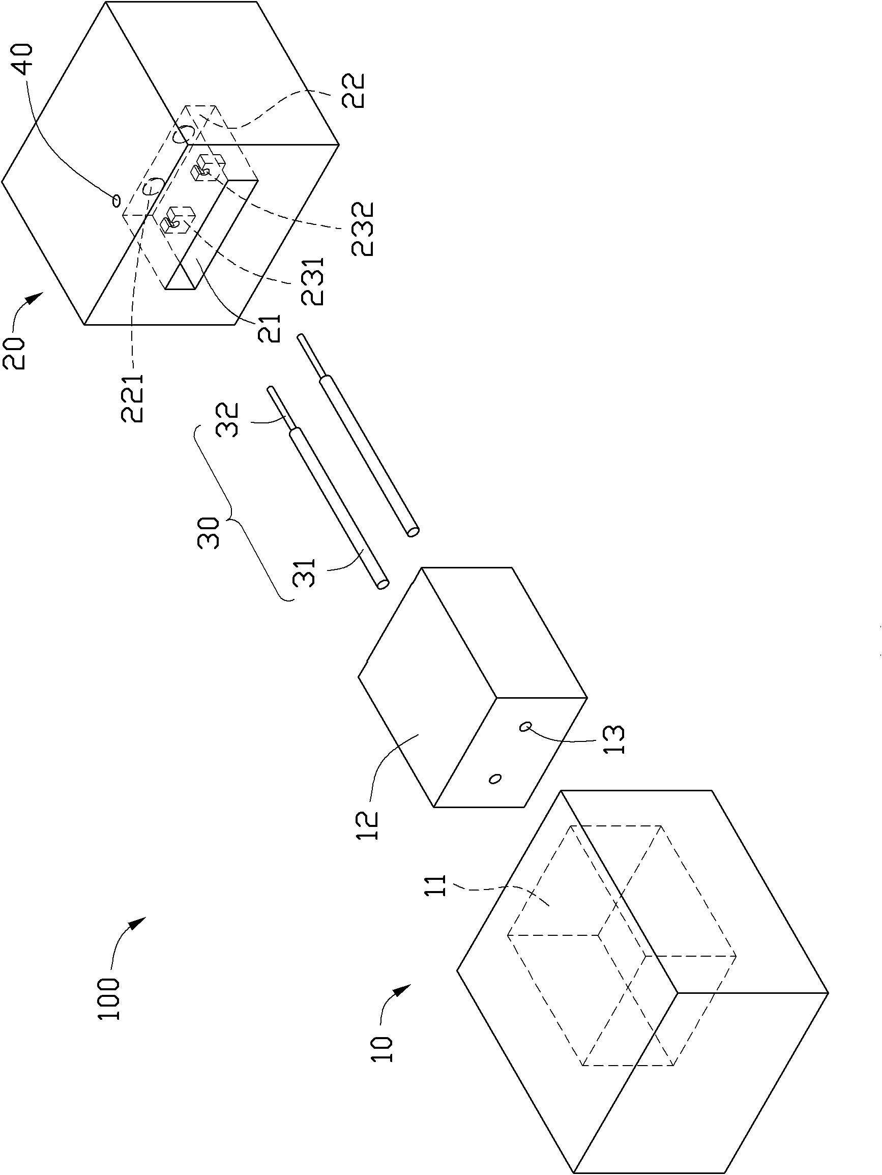
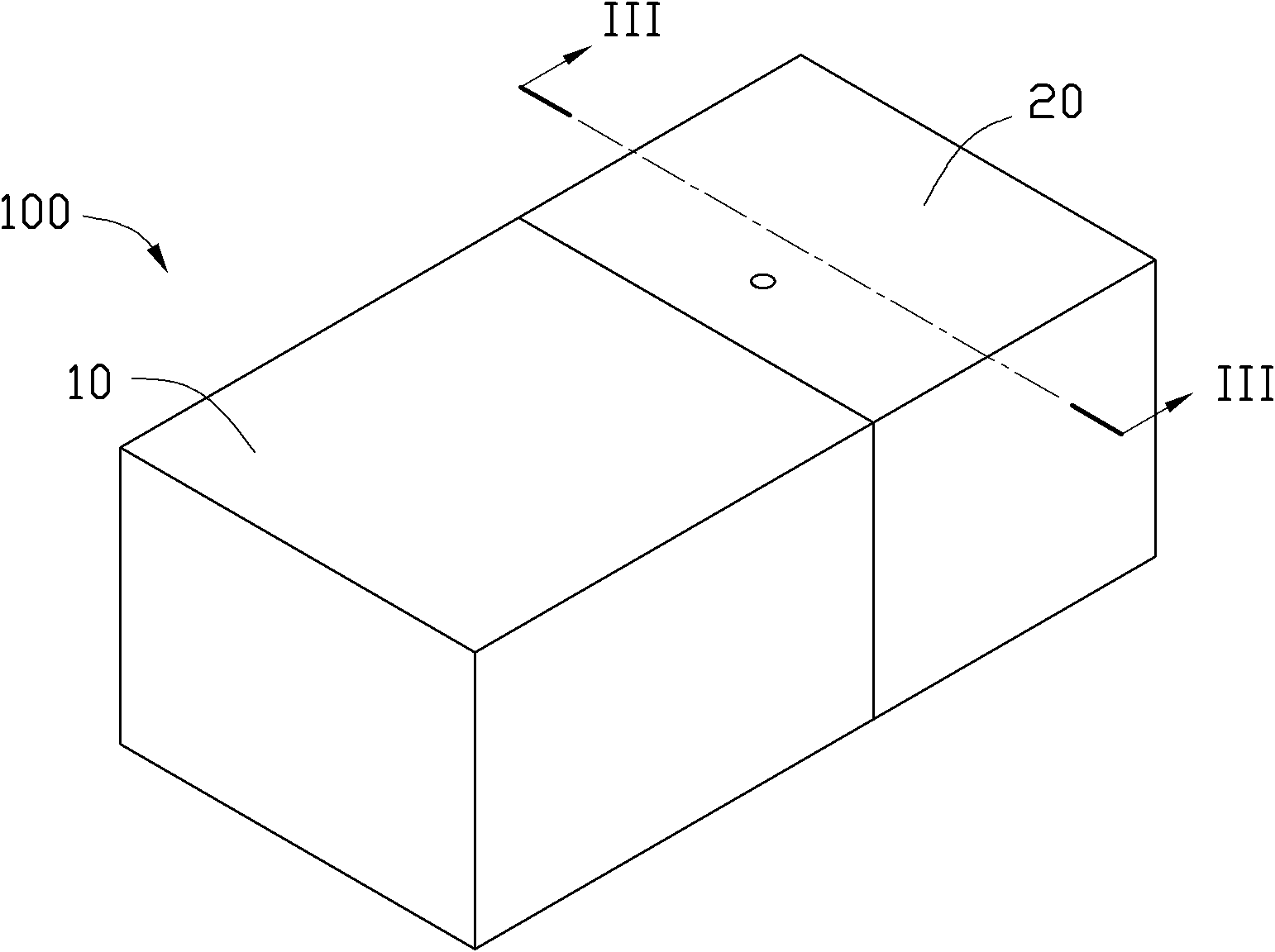
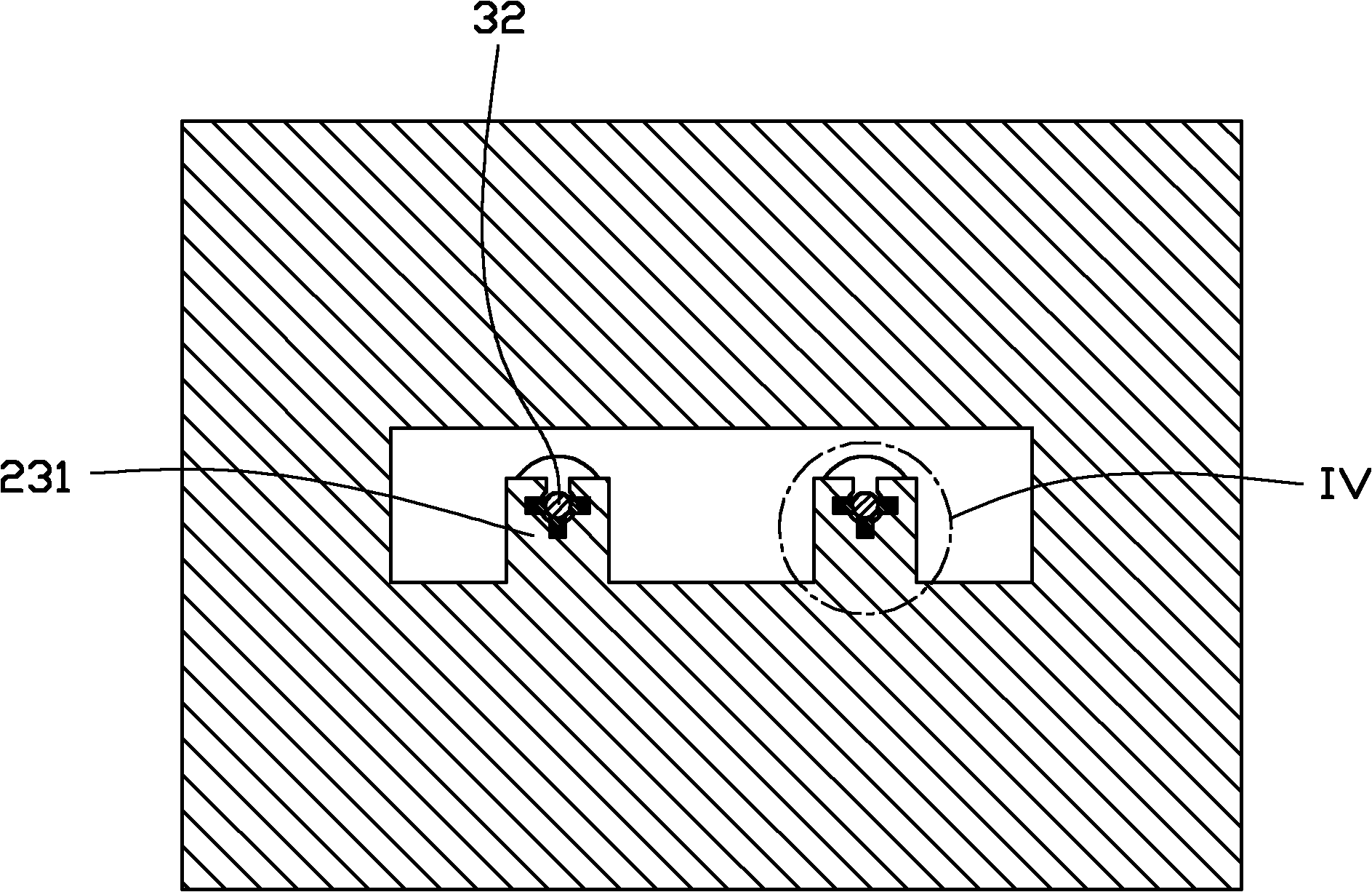
[0033] Please also see Figure 1 to Figure 4 , the mold 100 provided by the embodiment of the present invention is used to form a fiber coupling connector (not shown in the figure), and the fiber coupling connector includes a blind hole for accommodating an optical fiber and a lens optically coupled with the blind hole. The mold 100 includes a male mold 10, a female mold 20, and a core insert 30, wherein the core insert 30 has a tail portion 31 and a blind hole forming portion 32, and the blind hole forming portion 32 is used for forming the optical fiber coupling connector. Blind hole.

[0034] The male mold 10 is used for clamping and positioning the tail end of the mold core insert 30 . In this embodiment, the male mold 10 has a receiving cavity 11 and a fixing block 12 , and the receiving cavity 11 is used for receiving the fixing block 12 . The fixing...


PUM


Abstract

The invention relates to a die for molding a fiber coupling connector. The die comprises a mold insert which comprises a tail part and a blind hole molding part; a male mold for accepting and fixing the tail part of the mold insert; and a female mold which comprises a molding chamber possessing a lens molding part and a positioning block which is arranged in the lens molding chamber, corresponds to the lens molding part and is used for clamping and positioning the blind hole molding part to aim the blind hole molding part at the center of the lens molding part. Compared with the prior art, the die allows the mold insert to be clamped and positioned through the positioning block, so the collimation of the blind hole is substantially increased.

Description

technical field [0001] The invention relates to a mold for forming an optical fiber coupling connector. Background technique [0002] Fiber coupling connectors are generally equipped with a blind hole and a lens. The blind hole is used to accommodate the optical fiber. The lens is located at the bottom of the blind hole to optically couple with the fiber. The coupling degree between the blind hole and the lens directly determines the optical fiber. Transmission efficiency of coupled connectors. [0003] At present, injection molding is a commonly used method for making optical fiber coupling connectors, and the molds used for injection molding usually include mold inserts for forming blind holes, and mold inserts that match with the mold inserts and have lens molding parts. cavity, and the mold core fits with the forming cavity to form the optical fiber coupling connector. [0004] However, the central axis of the blind hole of the optical fiber coupling connector molded b...

Claims


Application Information

Patent Timeline
Patent Type & Authority Applications(China)
IPC IPC(8): B29C45/26B29L11/00
Inventor 林奕村
Owner JIANGSU STERLITE TONGGUANG FIBER
Why Eureka
Try Eureka