Fuel tank structure

A fuel tank and fuel oil technology, applied in the direction of the lower structure, can solve the problems of poor sealing and easy outward overflow, and achieve the effect of eliminating the overflow phenomenon

Inactive Publication Date: 2011-11-23
SANY AUTOMOBILE HOISTING MACHINERY
View PDF6 Cites 8 Cited by
  • Summary
  • Abstract
  • Description
  • Claims
  • Application Information

AI Technical Summary

Problems solved by technology

[0003] With the fuel tank structure in the prior art, although there are gaskets at the filler caps and filler ports of the main and auxiliary fuel tanks, they are not tightly sealed. When the vehicle rolls or tilts forward and backward, the main and auxiliary fuel tank The fuel oil with high liquid level in the interior affects each other, and it is easy to overflow outward

Method used


Image

  • Fuel tank structure
  • Fuel tank structure
  • Fuel tank structure

Examples


Embodiment Construction

[0029] The following will clearly and completely describe the technical solutions in the embodiments of the present invention with reference to the accompanying drawings in the embodiments of the present invention. Obviously, the described embodiments are only some, not all, embodiments of the present invention. Based on the embodiments of the present invention, all other embodiments obtained by persons of ordinary skill in the art without creative efforts fall within the protection scope of the present invention.

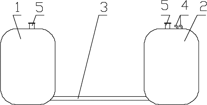
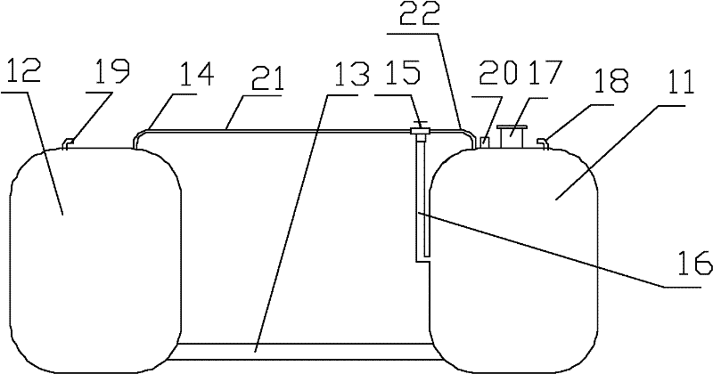
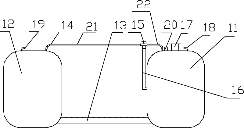
[0030] refer to figure 2 , in the first embodiment of a fuel tank structure of the present invention, the fuel tank structure includes a main fuel tank 11 and an auxiliary fuel tank 12, the lower end of the main fuel tank 11 and the auxiliary fuel tank 12 The lower end communicates with a fuel pipe 13 , and the fuel tank structure also includes a vent pipe 14 and a balance pipe 16 .

[0031] The vent pipe 14 is used to connect the upper end of the main fuel tank ...


PUM


Abstract

The invention provides a fuel tank structure. The fuel tank structure comprises a main fuel tank, an auxiliary fuel tank, vent pipes and a balance pipe, wherein the vent pipes are used for connecting the upper end part of the main fuel tank with the upper end part of the auxiliary fuel tank and comprise a first vent pipe, a second vent pipe and a control device which is provided with at least three connecting openings; one end of the first vent pipe is connected with the main fuel tank, and the other end of the first vent pipe is connected with one end of the second vent pipe through two connecting openings of the control device; the other end of the second vent pipe is connected with the auxiliary fuel tank; the control device is used for controlling the first vent pipe and the second vent pipe to be opened/closed; one end of the balance pipe is connected with a third connecting opening of the control device, and the other end of the balance pipe is connected with the main fuel tank;and the control device is also used for controlling the first vent pipe and the balance pipe to be opened/closed. In the fuel tank structure, a pressure difference principle is utilized, so that overflow phenomena of the fuel tanks can be eliminated to the maximum extent.

Description

technical field [0001] The invention relates to the field of engineering machinery, in particular to a fuel tank structure. Background technique [0002] In the design process of large-scale automobiles, large-tonnage truck cranes and other construction machinery, under the premise of satisfying the space layout and cruising range, the fuel tank structure in the power system of the off-board chassis usually adopts the setting method of main and auxiliary fuel tanks. The setting method is as figure 1 As shown, the main components include a left auxiliary fuel tank 1, a right main fuel tank 2, and a lower oil pipe 3. Wherein, the main fuel tank on the right side is provided with an outlet / return pipe interface 4, and both the main fuel tank and the auxiliary fuel tank are provided with filling ports 5. During the working process of the fuel tank structure, fuel can be injected into the fuel tank through the filler port on any fuel tank on both sides, and the fuel in the fuel...

Claims


Application Information

Patent Timeline
Patent Type & Authority Applications(China)
IPC IPC(8): B60K15/03
Inventor 邢斌钟明辉汪谦胜
Owner SANY AUTOMOBILE HOISTING MACHINERY
Why Eureka
Try Eureka