Supercharge Your Innovation With Domain-Expert AI Agents!

Forming device for plastic ampoule

A molding device and ampoule technology, applied in the field of medical packaging equipment, can solve the problem of no molding device and the like, and achieve the effects of simple operation, high molding quality and low cost

Active Publication Date: 2012-11-07
TRUKING TECH LTD
View PDF0 Cites 0 Cited by
  • Summary
  • Abstract
  • Description
  • Claims
  • Application Information

AI Technical Summary

Problems solved by technology

However, there is currently no molding device for such plastic ampoules

Method used


Image

  • Forming device for plastic ampoule
  • Forming device for plastic ampoule
  • Forming device for plastic ampoule

Examples


Embodiment Construction

[0024] The present invention will be further described in detail below in conjunction with the accompanying drawings and specific embodiments.

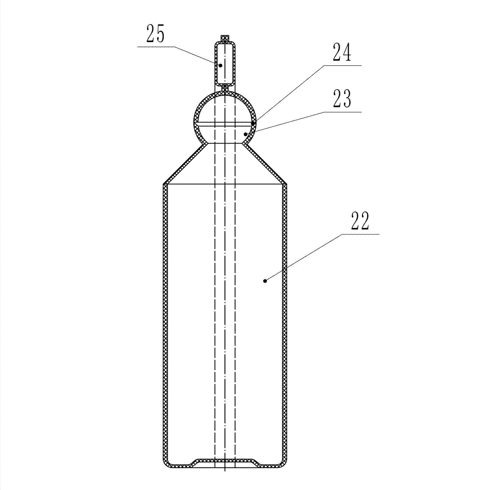
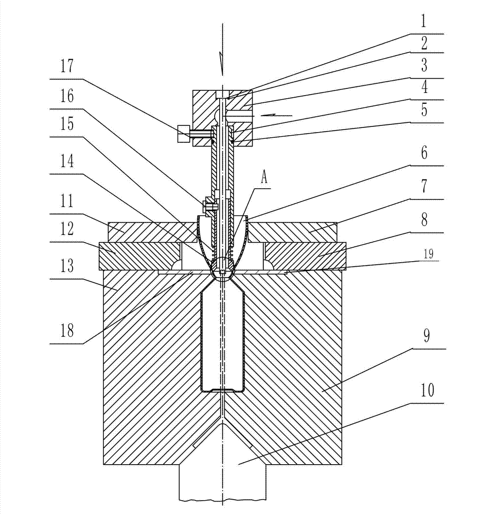
[0025] Such as image 3 , Figure 4 and Figure 5 As shown, the molding device of the plastic ampoule of the present invention includes a pressure head assembly and a molding assembly that cooperate with each other. On the pressure head assembly, one end facing the molding assembly is provided to cooperate with the molding assembly to form a twist-off groove on the inner wall of the bottle blank 6 24 wedge surface, and then form the built-in twist-off groove 24.

[0026] In this embodiment, the molding assembly includes a left main mold 13, a right main mold 9, a left liner 18 and a right liner 19, the left liner 18 is installed in the groove on the upper part of the left main mold 13, and the right liner 19 is installed in In the groove on the right main mold 9 top, the liner plate works together with the pressure head assembly to...


PUM


Abstract

The invention discloses a forming device for a plastic ampoule. The device comprises a pressure head component and a forming component which are matched with each other, wherein the end of the pressure head component, which faces the forming component, is provided with a wedge surface which is matched with the forming component to form a twist-off groove on the inner wall of a bottle blank. The forming device has the advantages of simple and compact structure, low cost, high forming quality and the like, and is easy and convenient to operate.

Description

technical field [0001] The invention mainly relates to the field of medical packaging equipment, in particular to a molding device for plastic ampoules. Background technique [0002] Ampoule is a small container used to hold liquid medicine, which can be made of glass or plastic. Such as figure 1 As shown, in order to make the ampoule easy to open during use, the existing plastic ampoule is generally provided with an annular twist-off groove 24 on the outer peripheral side of its ampoule head 23, and a top end of the ampoule head 23 is provided with a Knob 25 for easy operation. When in use, twist the knob 25 by hand, and the ampoule head 2 will be twisted off along the twisting groove 24 . However, in the above structure, the twist-off grooves 24 are all external, and stolen goods and bacteria are easy to hide therein, and it is not easy to clean and disinfect, so there is a potential safety hazard. Such as figure 2 As shown, some practitioners have proposed a new con...

Claims


Application Information

Patent Timeline
Patent Type & Authority Patents(China)
IPC IPC(8): B67C7/00B26D3/08
Inventor 王业洲詹文中邓京良李新华周飞跃
Owner TRUKING TECH LTD
Features
  • R&D
  • Intellectual Property
  • Life Sciences
  • Materials
  • Tech Scout
  • Unparalleled Data Quality
  • Higher Quality Content
  • 60% Fewer Hallucinations
Learn More