
Conical friction ring transmission and method for continuously transmitting torque by means of conical friction ring transmission

A technology of friction rings and transmissions, which is applied in the direction of friction transmissions, transmissions, belts/chains/gears, etc., which can solve problems such as large structures and achieve the effect of reducing the structure volume

Inactive Publication Date: 2016-01-20
乌尔里克·罗斯
View PDF10 Cites 0 Cited by
  • Summary
  • Abstract
  • Description
  • Claims
  • Application Information

AI Technical Summary

Problems solved by technology

[0006] Although the aforementioned conical friction ring transmissions effectively achieve the purpose of infinitely variable adjustment of the torque to be transmitted, especially if they have a guide device or a control device with a relatively small friction ring structure required for this, However, the known conical friction ring transmission is always structurally large enough due to its relatively large friction cone bearings

Method used


Image

  • Conical friction ring transmission and method for continuously transmitting torque by means of conical friction ring transmission
  • Conical friction ring transmission and method for continuously transmitting torque by means of conical friction ring transmission
  • Conical friction ring transmission and method for continuously transmitting torque by means of conical friction ring transmission

Examples


Embodiment Construction

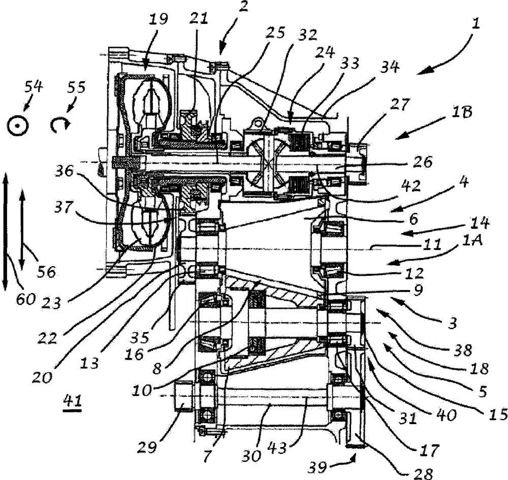
[0041] figure 1 The transmission 1 shown basically comprises two transmission stages 1A, 1B, which can be shifted selectively via a synchronized transmission 2 into a drive train. In this case, the first transmission stage 1A has a conical friction ring transmission 3 with two oppositely arranged friction cones 4 , 5 , wherein the first friction cone 4 is the input friction cone 6 of the conical friction ring transmission 3 And the second friction cone 5 is the output friction cone 7 . Two friction cones 4,5 are arranged in this way, so that friction ring 9 rings are embedded in the gap 8 of friction cone 4 running between the friction cones 4,5.

[0042] In order for the conical friction ring transmission 3 to be able to transmit particularly high torques, the friction cone 5 additionally includes in this exemplary embodiment a hold-down device 10 not described in detail here, which holds the two friction cones 4 and 5 together. The friction ring 9 is tensioned under a vari...


PUM


Abstract

In order to make the structure of the cone friction ring transmission more compact, the present invention proposes a cone friction ring transmission, which has a first friction cone, a second friction cone, a friction ring and at least one other transmission part, wherein the first friction cone a first friction cone bearing is rotatably mounted about the axis of the first friction cone bearing and a second friction cone is rotatably mounted about the axis of the second friction cone bearing by means of a second friction cone bearing, wherein the two friction cones are arranged in tension with each other by means of a friction ring, The main bearing force acting radially with respect to the friction cone bearing axis extends in the main bearing plane spread out by the two friction cone bearing axes, and at least one further transmission element is connected in front of or behind the friction cone and in which A coupling torque can act between one of the friction cones and at least one further transmission element, and the reaction force generated by the coupling torque is directed opposite to the main bearing force in the main bearing plane.

Description

technical field [0001] The invention relates to a conical friction ring transmission with a first friction cone, a second friction cone, a friction ring and at least one further transmission element, wherein the first friction cone surrounds the first friction cone bearing by means of a first friction cone bearing The axis is mounted in rotation and the second friction cone is mounted in rotation around the axis of the second friction cone bearing by means of a second friction cone bearing, wherein the two friction cones are arranged tensioned against one another by means of friction rings, wherein the main force acting radially with respect to the axis of the friction cone bearing The bearing force extends in a main bearing plane developed by the bearing axes of the two friction cones, wherein at least one further transmission element is connected in front of or behind the friction cone and wherein between one of the friction cones and the at least one further transmission ele...

Claims


Application Information

Patent Timeline
Patent Type & Authority Patents(China)
IPC IPC(8): F16H15/42F16H37/02
CPCF16H15/42F16H37/021F16H15/06F16H15/16F16H15/18F16H15/22
Inventor 乌尔里克·罗斯C·德雷格尔
Owner 乌尔里克·罗斯
Learn More