
Normal-temperature humidity control storage cabinet

A humidity control and storage cabinet technology, which is applied in the field of storage cabinets, can solve the problems that the moisture-proof box and drying box cannot meet the demand, the humidity requirement cannot be met, and the raw materials are unfavorable, so as to improve the efficiency of drainage and dehumidification, and the stability of the refrigeration cycle air duct , the effect of improving the efficiency of refrigeration

Active Publication Date: 2011-11-23
HANGZHOU BONHONG OPTOELECTRONICS TECH
View PDF6 Cites 2 Cited by
  • Summary
  • Abstract
  • Description
  • Claims
  • Application Information

AI Technical Summary

Problems solved by technology

Today's ordinary moisture-proof boxes and drying boxes on the market are increasingly unable to meet the needs
Ordinary moisture-proof drying ovens use PTC heating to regenerate hygroscopic materials. This has a great design flaw, because during the heating and regeneration process, the temperature of the entire storage space rises by about 5°C compared to the ambient temperature. The position temperature of the dehumidification host is as high as 40°C-55°C, which will cause adverse effects on raw materials
[0003] Although ordinary dehumidifiers will not increase the ambient temperature, they can only work on the ambient humidity in large airspaces such as warehouses, and there will be some dehumidification dead ends; the humidity can only be controlled at about 45% RH, which cannot reach Higher humidity requirements, and the accuracy of humidity control is not high

Method used


Image

  • Normal-temperature humidity control storage cabinet
  • Normal-temperature humidity control storage cabinet
  • Normal-temperature humidity control storage cabinet

Examples


Embodiment Construction

[0020] The technical solution of the present invention will be further specifically described below in conjunction with the accompanying drawings.

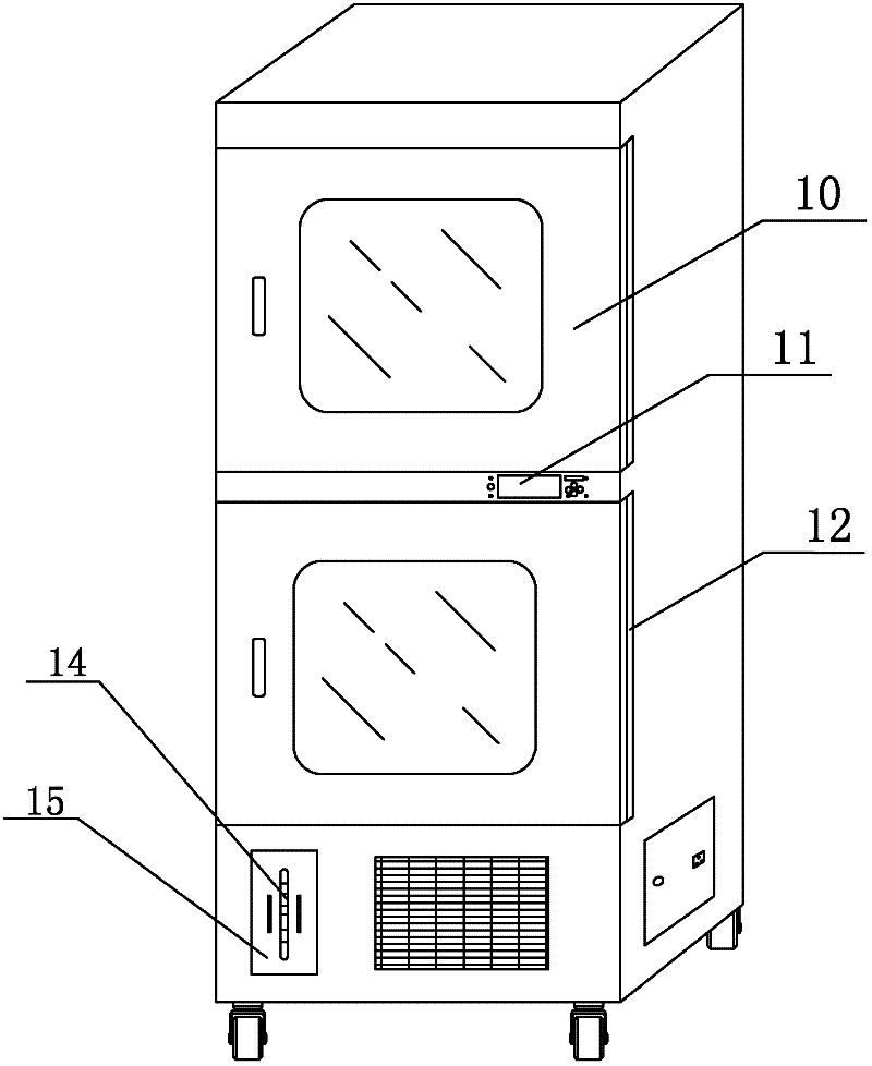
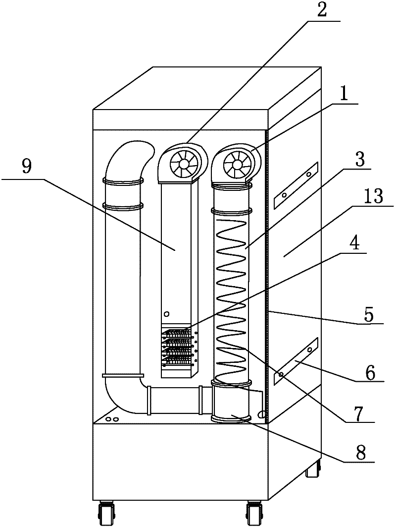
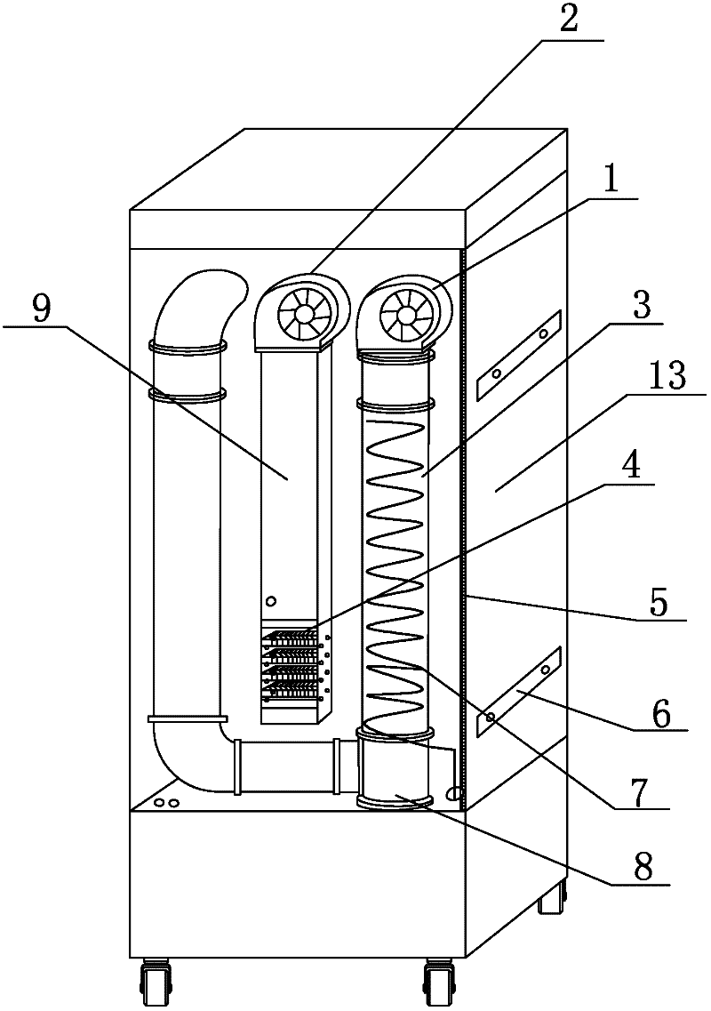
[0021] Such as figure 1 , 2 , a storage cabinet with humidity control at normal temperature, comprising an airtight cabinet body 13, a U-shaped refrigeration circulation air duct 3 is arranged on the airtight cabinet body 13, and one side of the U-shaped refrigeration circulation air duct 3 is sequentially provided with Air cooler 1, spiral refrigeration pipe 7, drain pipe 8, the refrigeration pipe 7 is connected to the refrigeration compressor, the lower end of the drain pipe 8 is connected to the water tank 15, the other side of the U-shaped refrigeration circulation air duct 3 passes through the cold air outlet and the airtight cabinet 13 communicated; the airtight cabinet body 13 is also provided with a heating circulation air duct 9, and the heating circulation air duct 9 is sequentially provided with a hot air blower 2, a h...


PUM


Abstract

The invention discloses a normal-temperature humidity control storage cabinet which comprises an enclosed cabinet body; the enclosed cabinet body is provided with a U-shaped refrigeration cycle air channel; one side of the U-shaped refrigeration cycle air channel is provided with an air cooler, a spiral refrigeration pipeline and a drain pipe sequentially from top to bottom; the refrigeration pipeline is connected with a refrigeration compressor; the lower end of the drain pipe is connected with a water tank; the other side of the U-shaped refrigeration cycle air channel is communicated with the enclosed cabinet body through a cold air opening; the enclosed cabinet is also provided with a heating cycle air channel; the heating cycle air channel is sequentially provided with an air heater, a heating block and a hot air opening from top to bottom; and the heating cycle air channel is communicated with the enclosed cabinet body through the hot air opening. The refrigeration cycle air channel is arranged in a U shape, the cold air opening is arranged on the left side, the air cooler is arranged on the right side; by adoption of the U-shaped arrangement, the refrigeration is more uniform, accumulated water in the refrigeration cycle air channel can be discharged in time, but can not flow back to the cabinet body, thus the refrigeration cycle air channel is ensured to be more stable.

Description

technical field [0001] The invention relates to a storage cabinet, in particular to a humidity control cabinet. Background technique [0002] With the development of science and technology, the storage of precision components has higher and higher requirements for temperature and humidity control. The ordinary moisture-proof boxes and drying boxes on the market today are increasingly unable to meet the demand. Ordinary moisture-proof drying ovens use PTC heating to regenerate hygroscopic materials. This has a great design flaw, because during the heating and regeneration process, the temperature of the entire storage space rises by about 5°C compared to the ambient temperature. The position temperature of the dehumidification host is as high as 40°C-55°C, which will have an adverse effect on raw materials. [0003] Although ordinary dehumidifiers will not increase the ambient temperature, they can only work on the ambient humidity in large airspaces such as warehouses, and...

Claims


Application Information

Patent Timeline
Patent Type & Authority Applications(China)
IPC IPC(8): F25D31/00F25D17/06
Inventor 李新华
Owner HANGZHOU BONHONG OPTOELECTRONICS TECH
Learn More