
An appearance structure of an electromagnetic pen

An electromagnetic pen and shape technology, which is applied to the input/output process of electrical digital data processing, instruments, and data processing, etc., can solve the problems of inconvenient maintenance, complex structure, low utilization rate, etc., and achieve convenient charging and convenient device assembly. , a strong overall effect

Active Publication Date: 2016-08-03
北京南昊科技股份有限公司
View PDF4 Cites 0 Cited by
  • Summary
  • Abstract
  • Description
  • Claims
  • Application Information

AI Technical Summary

Problems solved by technology

[0003] (1) The structure is relatively complex, assembled from multiple parts separated from each other, with poor integrity, inconvenient maintenance, and fear of falling;
[0004] (2) The function is single, only one end of the pen can be used to realize the function, and the other end needs to be equipped with a battery, so the utilization rate is low
[0005] However, as the product matures, the number of users increases, and users put forward more and more requirements for the use of electromagnetic pens. The structure of the electromagnetic pens currently on the market cannot meet the needs of more and more consumers. Therefore, there is a need for an electromagnetic pen with a simple structure, easy assembly and maintenance, which can be powered by an electric energy storage device or a power generation device instead of a battery, and is time-saving and convenient to charge, and can be equipped with a signal transmission device at both ends of the pen. structure

Method used

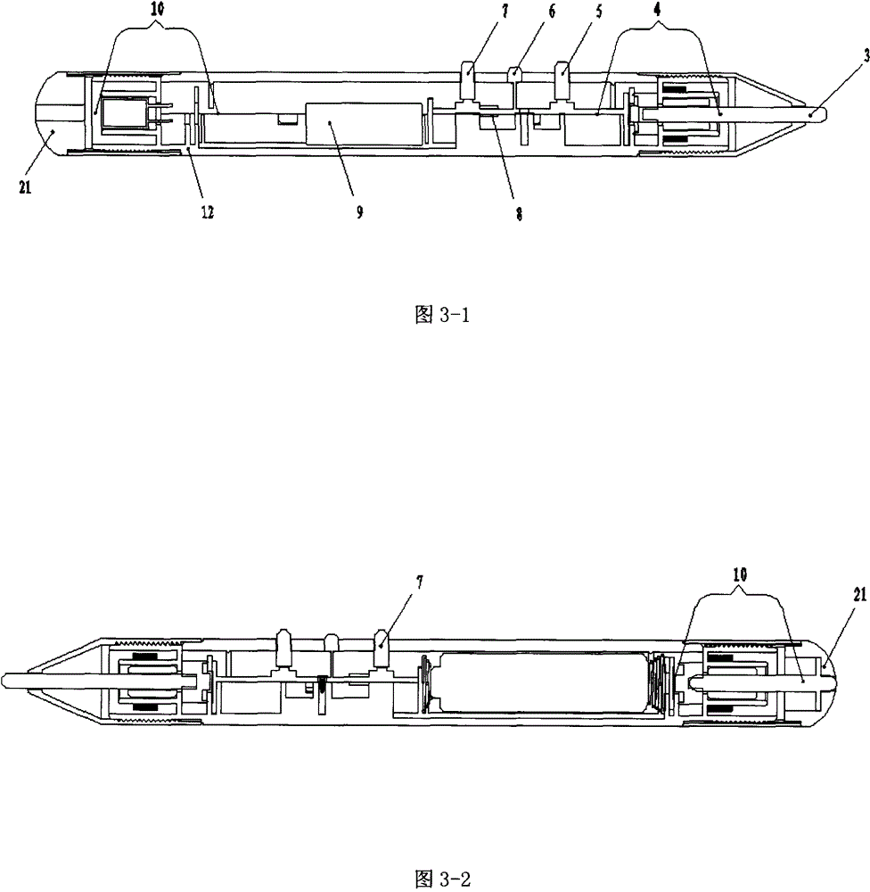

Image

  • An appearance structure of an electromagnetic pen
  • An appearance structure of an electromagnetic pen
  • An appearance structure of an electromagnetic pen

Examples


Embodiment Construction

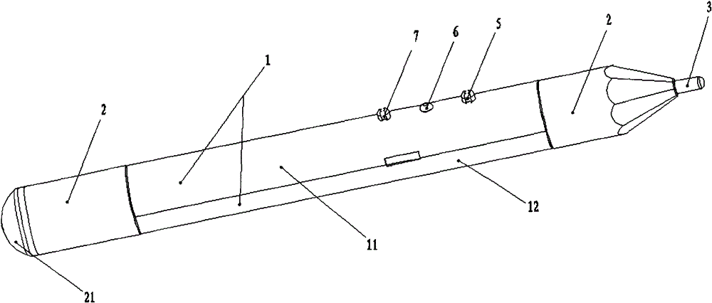
[0029] Such as figure 1 Shown is the appearance and external structure diagram of the electromagnetic pen of the present invention. The penholder 1 is formed by buckling two semi-cylindrical skeletons, that is, the shield 11 and the main body 12. The nib coat 2 is respectively connected to the two ends of the penholder 1. One of the ends is silicone rubber 21, and the top of the silicone rubber 21 is provided with a through hole along the direction of the pen holder. In addition, the electromagnetic pen of this invention is also equipped with a front-end signal control button 5, a rear-end signal control button 7, a power supply or signal Indicator light 6 and nib 3. A complete pen holder 1 is coupled with the nib coat 2 at both ends, the nib 3, the circuit and various devices on the main body 12, and a complete professional electromagnetic pen is formed.

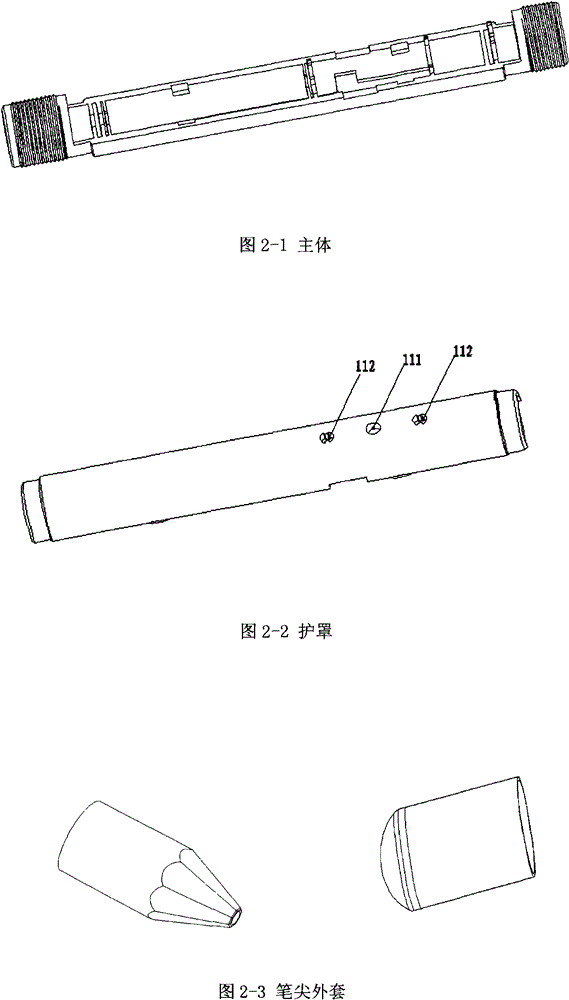
[0030] Such as figure 2 As shown, it is a diagram of the main parts of the electromagnetic pen of the present inventio...


PUM


Abstract

The invention relates to an appearance structure of an electromagnetic pen. The electromagnetic pen is a pen-like tool for writing and operating on the electromagnetic whiteboard. The shape and structure of the electromagnetic pen includes a pen holder and a pen tip coat, wherein the pen holder of the electromagnetic pen is composed of a main body and a shield, and the two are buckled together to form a whole pen holder. The technical solution adopted in the present invention is: the pen holder adopts a "two-in-one" structure, which is integrated by the main body and the shield, and the two ends are screwed together with the nib jacket to form an integral body, and there is enough space for the power supply device in the middle part of the pen holder. In addition to being powered by batteries, it can also be equipped with other electric energy storage devices or power generation devices. There are charging electrodes on both sides of the pen holder to facilitate charging; the circuit assembly space is reserved on both sides of the pen holder to ensure that both ends of the pen can realize electrical performance.

Description

technical field [0001] The patent of the present invention relates to an input structure of an electromagnetic smart whiteboard, in particular to an appearance structure of an electromagnetic pen. Background technique [0002] At present, many electronic whiteboard products on the market are operated by professional electromagnetic pens, which are equipped with designed circuits and special devices inside the electromagnetic pens. According to investigations and studies, the electromagnetic pens currently on the market that can be used on electronic whiteboards have the following disadvantages: [0003] (1) The structure is relatively complex, assembled from multiple parts separated from each other, with poor integrity, inconvenient maintenance, and fear of falling; [0004] (2) The function is single, only one end of the pen can be used to realize the function, and the other end must be assembled with a battery, so the utilization rate is low. [0005] However, as the pro...

Claims


Application Information

Patent Timeline
Patent Type & Authority Patents(China)
IPC IPC(8): G06F3/0354
Inventor 王志明
Owner 北京南昊科技股份有限公司
Learn More