
Method and device for diagnosing transmission network failure

A fault diagnosis device and fault diagnosis technology, applied in transmission systems, digital transmission systems, data exchange networks, etc., can solve problems such as difficulty in analyzing and locating faults, network management systems cannot communicate with each other, and root fault diagnosis cannot be performed

Inactive Publication Date: 2011-11-23
GUANGDONG POWER GRID POWER DISPATCHING CONTROL CENT
View PDF4 Cites 29 Cited by
  • Summary
  • Abstract
  • Description
  • Claims
  • Application Information

AI Technical Summary

Problems solved by technology

According to the existing alarm methods, a large number of alarms may be generated when a fault occurs in the network. Usually, the number of alarms in a large transmission network can reach as many as one million a day. Faced with such a large number of alarms For network administrators, it is becoming increasingly difficult to quickly and accurately analyze and locate faults from a large number of alarms. The reason is that the alarm sequence caused by the fault contains meaningless alarms and redundant alarms, and In addition to meaningless and redundant alarms that may appear repeatedly, for the same subnet, if a communication entity fails and reports an alarm, it will affect other dependent communication entities to also report alarms. If only the The causal relationship between faults and alarms, without combining the causal relationship with the dependencies of communication entities, will not be practical in the alarm correlation of the actual transmission network. In addition, for multi-layer transmission networks, the lower layer Faults in the network often have an impact on the upper-layer network. Because the information between the network management systems of different layers of the network cannot communicate with each other, the reported alarm information often contains incomplete data, so it is impossible to diagnose the root fault of the entire network.

Method used


Image

  • Method and device for diagnosing transmission network failure
  • Method and device for diagnosing transmission network failure
  • Method and device for diagnosing transmission network failure

Examples


Embodiment Construction

[0020] The solutions of the present invention are described in detail below in conjunction with specific examples.

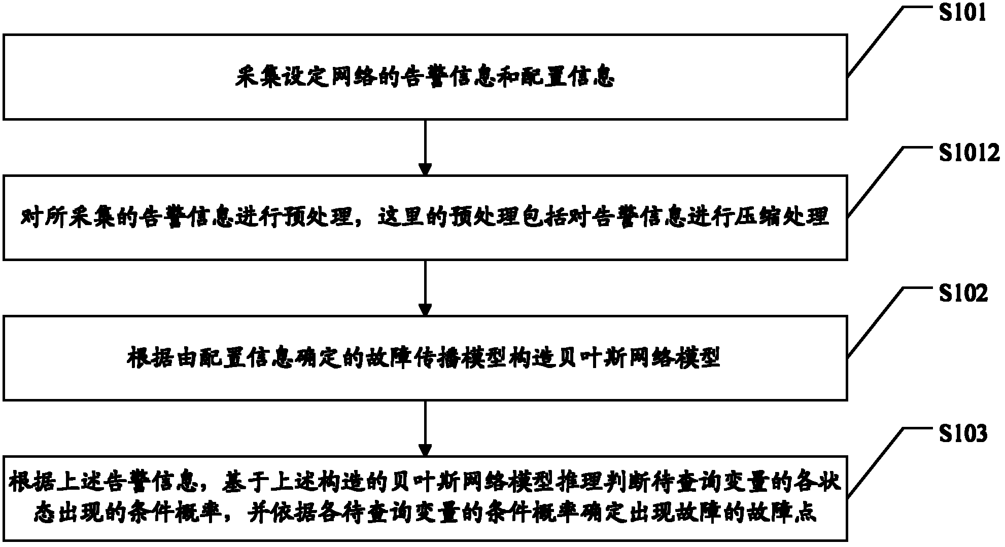
[0021] see figure 1 As shown, it is a schematic flow diagram of an embodiment of the transmission network fault diagnosis method of the present invention, which includes steps:

[0022] Step S101: collect alarm information and configuration information of the set network, where the configuration information includes network element layer information and network connection layer information, and enter step S102;

[0023] Step S102: Construct a Bayesian network model according to the fault propagation model determined by the configuration information. The construction process includes: corresponding to each node in the fault propagation model, defining a set of variables of the Bayesian network, corresponding to each node in the fault propagation model For each directed edge, define a directed edge of the Bayesian network, and initialize and define the prior prob...


PUM


Abstract

The invention discloses a method and device for diagnosing a transmission network failure. The method comprises the following steps of: acquiring alarm information and configuration information of a set network, wherein the configuration information comprises network element layer information and network connection layer information; configuring a Bayes network model according to a failure propagation model determined by using the configuration information: defining a group of variables of a Bayes network corresponding to each node in the failure propagation model, defining a directed edge of the Bayes network corresponding to each directed edge in the failure propagation model, and initializing the prior probability of each root node and the conditional probability of each directed edge in the Bayes network; and reasoning and judging the conditional probability of the occurrence of each status of each variable to be inquired based on the Bayes network model according to the alarm information, and determining a failure point according to the conditional probability status of each variable to be inquired. According to the scheme disclosed by the invention, the failure point can be positioned accurately; and the method and the device have high operability.

Description

technical field [0001] The invention relates to a fault diagnosis method for a transmission network and a fault diagnosis device for a transmission network. Background technique [0002] Faults are unavoidable in the transmission network. When a fault occurs, a corresponding alarm message will be issued. According to the existing alarm methods, a large number of alarms may be generated when a fault occurs in the network. Usually, the number of alarms in a large transmission network can reach as many as one million a day. Faced with such a large number of alarms For network administrators, it is becoming increasingly difficult to quickly and accurately analyze and locate faults from a large number of alarms. The reason is that the alarm sequence caused by the fault contains meaningless alarms and redundant alarms, and In addition to meaningless and redundant alarms that may appear repeatedly, for the same subnet, if a communication entity fails and reports an alarm, it will ...

Claims


Application Information

Patent Timeline
IPC IPC(8): H04L12/24
Inventor 蒋康明林斌李伟坚何杰李溢杰
Owner GUANGDONG POWER GRID POWER DISPATCHING CONTROL CENT
Learn More