Electric carrier wave lighting control system

A power carrier and control system technology, applied in distribution line transmission system, lamp circuit layout, electric light source, etc., can solve the problems of cumbersome investigation, low efficiency, time-consuming and laborious, etc., to increase economic benefits and management quality, improve The effect of the level of automation management

Inactive Publication Date: 2011-11-23
XIDIAN UNIV
View PDF5 Cites 2 Cited by
  • Summary
  • Abstract
  • Description
  • Claims
  • Application Information

AI Technical Summary

Problems solved by technology

Therefore, the troubleshooting work in the traditional method is very cumbersome, time-consuming and laborious, and the efficiency is low

Method used


Image

  • Electric carrier wave lighting control system
  • Electric carrier wave lighting control system
  • Electric carrier wave lighting control system

Examples


Embodiment 1

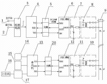
[0019] Such as figure 1 As shown, this is an implementation mode suitable for a single railway signal light or multiple railway signal lights powered by the same power line.

[0020] It includes at least an outdoor unit and an indoor unit; a detection circuit 3 is electrically connected to the main filament 1 and the auxiliary filament 2 of the outdoor unit, and the detection circuit 3 is used to detect the working status of the main filament 1 and the auxiliary filament 2, and the main filament 1 and the auxiliary filament 2 are connected to each other. The working state information of auxiliary filament 2 is provided to the outdoor unit single-chip microcomputer 4, when the main filament 1 is working and the auxiliary filament 2 is on standby, the main filament 1 is working normally, and the outdoor unit single-chip microcomputer 4 electrically connected with the detection circuit 3 obtains normal filament state information; When the filament 1 is working and the sub-filamen...

Embodiment 2

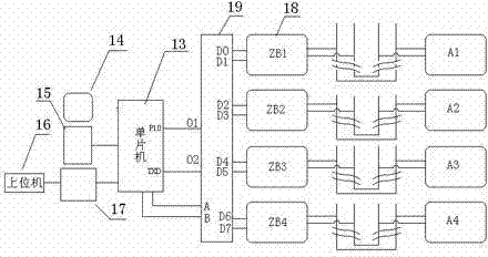
[0034] Such as figure 2 As shown, this is an implementation mode suitable for a single railway signal lamp or a railway signal lamp powered by multiple power lines.

[0035] Since embodiment 2 has the same circuit structure as embodiment 1, only the interface of the indoor unit adopts a plurality of power carrier circuits 18, and the plurality of power carrier circuits 18 are respectively electrically connected to the power line 9, so the following only applies to different indoor units. The machine interface circuit part is described.

[0036] Outdoor units A1, A2, A3, A4 are connected to different power lines 9, and the outdoor units A1, A2, A3, A4 have the same circuit structure, and the circuit is the same as figure 1 The same as in the description, it is used to detect the status of the main filament 1 and the sub-filament 2 of the railway signal lamp in different power line circuits, and transmit the status information of the main filament 1 and the sub-filament 2 thro...


PUM


Abstract

The invention relates to a control technique for a railway signal lamp and particularly relates to an electric carrier wave lighting control system. The system provided by the invention comprises an outdoor unit, an indoor unit and a detection circuit in the outdoor unit, wherein the detection circuit is electrically connected with the main filament and auxiliary filament of the outdoor unit; the detection circuit is used for detecting the working conditions of the main filament and the auxiliary filament; the detection circuit is electrically connected with electric wire carrier waves through a wave carrier of the outdoor unit; an electric wire is electrically connected with a control circuit of the indoor unit through a wave carrier of the indoor unit; when the main filament works and the auxiliary filament is standby, the main filament works normally and the control circuit of the indoor unit obtains normal filament state information; and when the auxiliary filament works and the main filament works abnormally, while reading that the main filament does not work or generates failures, the control circuit of the indoor unit gives out an alarm and simultaneously communicates with an upper computer through a communication interface circuit of the upper computer. The electric carrier wave lighting control system provided by the invention can be used for conveniently querying the main filament failures of the railway signal lamp.

Description

technical field [0001] The invention relates to the control technology of railway signal lamps, in particular to a power carrier lighting control system. Background technique [0002] Railway signal lights generally have backup filaments in case a single filament fails or fails to cause a major safety accident. Railway signal lights have two filaments, one primary and one secondary. When the main filament fails or fails, it is generally automatically switched to use the backup filament (secondary filament). When the main filament breaks, the backup filament will work instead. Under normal circumstances, the staff does not know which lamp in which position is faulty, so they can only check the lamps one by one, and replace them after finding a broken wire. Therefore, the troubleshooting work in the traditional method is very cumbersome, time-consuming and laborious, and the efficiency is low. Contents of the invention [0003] The purpose of the present invention is to ...

Claims


Application Information

Patent Timeline
Patent Type & Authority Applications(China)
IPC IPC(8): H05B37/02H05B37/04H04B3/54
Inventor 苗苗李智奇
Owner XIDIAN UNIV
Why Eureka
Try Eureka