Chassis with distributed jet cooling

A distributed and rack-based technology, applied in the field of thermal management systems, can solve problems such as increased heat transfer, new requirements, and limited data

Inactive Publication Date: 2011-11-23
GENERAL ELECTRIC CO
View PDF6 Cites 12 Cited by
  • Summary
  • Abstract
  • Description
  • Claims
  • Application Information

AI Technical Summary

Problems solved by technology

[0005] Limited data are available on the application of synthetic jets to large heat sink surfaces, although research suggests that the use of synthetic jets may increase heat transfer
In addition, a new connection device is required for a reliable connection of the synthetic jet to the frame

Method used


Image

  • Chassis with distributed jet cooling
  • Chassis with distributed jet cooling
  • Chassis with distributed jet cooling

Examples


Embodiment Construction

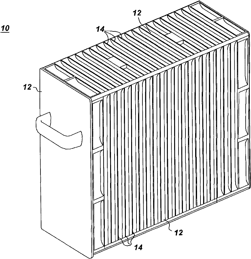
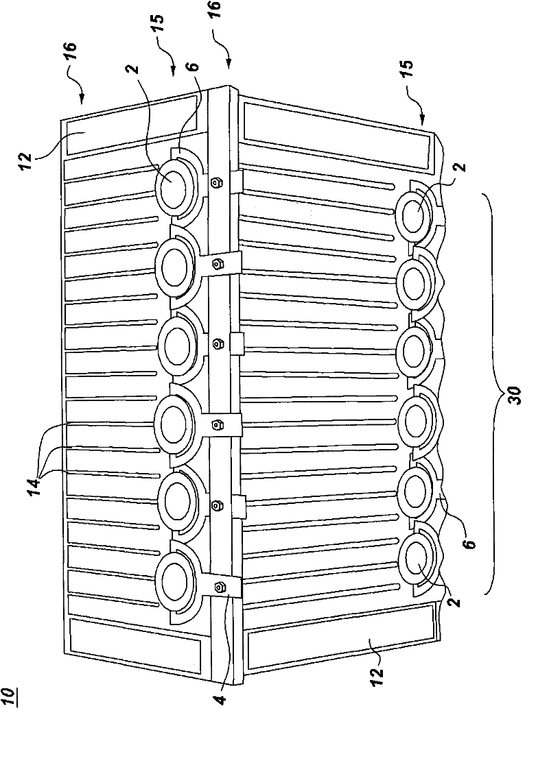
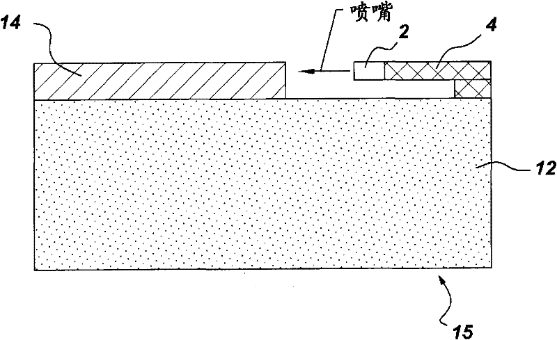
[0065] refer to Figure 1-17 A gantry 10 with distributed nozzle cooling is described. For example figure 1 As shown in , the housing 10 includes one or more side walls 12 defining a volume (not shown) configured to generally surround one or more heat-generating components (not shown) located within the volume. A heat generating component may be any component that requires cooling, non-limiting examples of which include high power processors and power electronics. The frame also includes at least one array of fins 14 thermally coupled to a respective one of the one or more side walls 12 . for figure 1 In the arrangement shown in , the fins 14 are longitudinal plate-like fins. However, other types of fins may also be used, including without limitation pin fins. In short, heat is transferred from the heat-generating component into the side walls, which in turn transfer heat into the fins 14 . Fins 14 increase the surface area for heat transfer to cool heat generating compo...


PUM


Abstract

A chassis (10) with distributed jet cooling is provided. The chassis includes one or more sidewalls (12) defining a volume configured to substantially surround one or more heat generating components positioned within the volume. The chassis further includes at least one array of fins (14) thermally coupled to a respective one of the one or more sidewalls and at least one synthetic jet assembly (30) comprising a multi-orifice synthetic jet (30) or a number of single orifice synthetic jets (2) disposed on a side (15, 16) of a respective one of the array(s) of fins. The chassis further includes at least one attachment means (4, 6, 9, 11, 20, 44) for attaching a respective one of the at least one synthetic jet assemblies to a respective one of the one or more sidewalls.

Description

technical field [0001] The present invention relates generally to thermal management systems, and more particularly, to thermal management systems with distributed nozzle cooling to increase convective heat transfer. Background technique [0002] Recent advances in electronics technology have produced nanometer-sized electronic circuits. The resulting advanced electronics, albeit smaller, have higher heat flux. Because thermal real estate is shrinking, advanced cooling techniques are required. Cost, size, reliability, and availability are major constraints. [0003] For many low power electronic applications, natural convection air cooling is the method of choice for reasons of cost, availability, and reliability. However, their performance is limited due to the buoyancy-dependent flow. Therefore, a further enhancement of natural convection is required in order to cool modern power electronics. Enhanced natural convection will allow for higher heat dissipation and still...

Claims


Application Information

Patent Timeline
Patent Type & Authority Applications(China)
IPC IPC(8): H05K7/20
CPCH05K7/20163H05K7/20172H05K7/20409
Inventor M·阿里克W·D·格斯特勒李日E·R·奈斯沃纳C·C·施勒德B·J·范德普勒格B·P·惠伦
Owner GENERAL ELECTRIC CO
Why Eureka
Try Eureka