Frontal sinus spacer

A gasket and paranasal sinus technology, applied in the field of medical devices, can solve problems such as delivery of interventional devices

Inactive Publication Date: 2011-11-23
ACCLARENT INC
View PDF39 Cites 7 Cited by
  • Summary
  • Abstract
  • Description
  • Claims
  • Application Information

AI Technical Summary

Problems solved by technology

Additionally, it may be difficult to deliver interventional devices deep into the frontal sinus cavity and there are difficulties associated with maintaining the interventional device within the frontal sinus outflow tract

Method used


Image

  • Frontal sinus spacer
  • Frontal sinus spacer
  • Frontal sinus spacer

Examples


Embodiment Construction

[0075] The following detailed description and drawings are intended to describe some, but not necessarily all, examples or embodiments of the invention. Nothing in this detailed description limits the scope of the invention in any way.

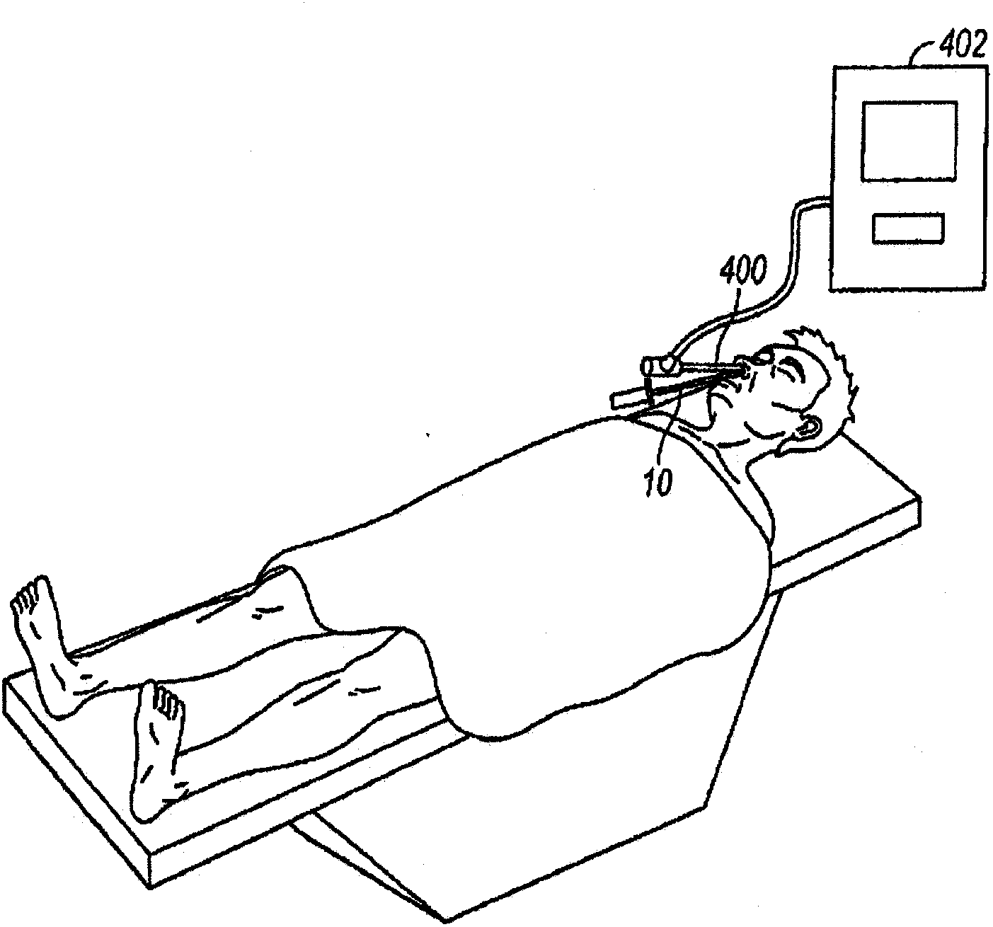
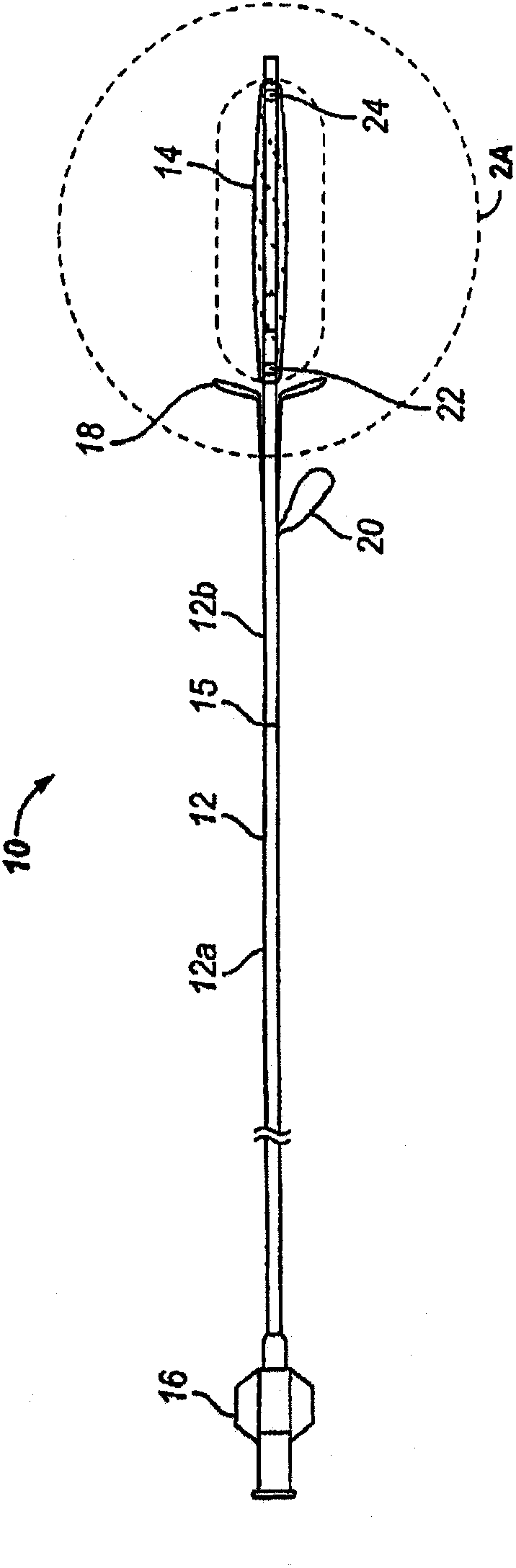
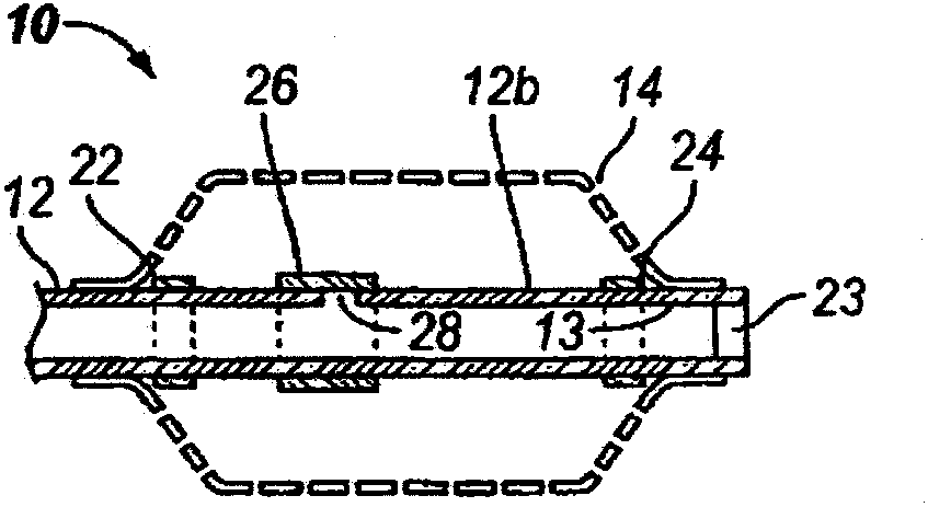
[0076] Figures 1 to 2G One embodiment of an implantable substance delivery device and / or spacer 10 of the present invention is shown. The device 10 has an elongated flexible catheter shaft 12 having a proximal portion 12a and a distal portion 12b that can be severed from each other at a spacing marker 15 . The proximal shaft portion 12a and the distal shaft portion 12b may be formed from the same or different materials, and may have the same or different dimensions (eg, diameter, wall thickness, etc.). For example, in some embodiments intended for implantation in a paranasal sinus or other ENT location, the proximal shaft portion 12a may be made of a suitable biocompatible material having sufficient breaking strength ( such as pushability)...


PUM


Abstract

Substance delivering spacer devices may comprise expandable reservoirs that are implantable in paranasal sinuses and other cavities, openings and passageways of the body to maintain patency and to provide sustained local delivery of a therapeutic or diagnostic substance. Delivery apparatus including elongate tubular members as well as shapeable distal portions and atraumatic tips are provided. Also provided are sinus penetrator devices and systems for performing ethmoidotomy procedures or for creating other openings in the walls of paranasal sinuses or other anatomical structures.

Description

[0001] Related Patent Applications [0002] This patent application is co-pending U.S. Patent Application 12 / 100,361 (filed April 9, 2008, entitled "Ethmoidotomy System And Implantable Spacer Devices Having Therapeutic Substance Delivery Capability For Treatment Of Paranasal Sinusitis" Ethmoid Sinusectomy System for Sinusitis and Implantable Spacer Device with Therapeutic Substance Delivery Capabilities)); co-pending U.S. Patent Application 12 / 100,361 is co-pending U.S. Patent Application 11 / 544,009 (filed October 4, 2006, entitled "Implantable Devices and Methods for Treating Sinusitis and Other Disorders"); common Pending U.S. Patent Application 11 / 544,009 is the application serial number 11 / 234,395 (filed September 23, 2005, entitled "Devices and Methods for Delivering Therapeutic Substances for the Treatment of Sinusitis and Other Disorders" (for Application Serial No. 11 / 234,395 is a continuation-in-part of Application Serial No. 11 / 037,548 (filed January 17, 2005, entitl...

Claims


Application Information

Patent Timeline
Patent Type & Authority Applications(China)
IPC IPC(8): A61M25/04A61B17/24A61F2/958
CPCA61M2025/0226A61M25/10A61M2025/0681A61B17/3421A61M2025/105A61M2210/0618A61M25/0075A61F11/004A61M29/02A61M25/04A61B17/3417A61B17/24A61M25/0084A61M2025/0008A61B2019/462A61B2090/062A61F11/20A61M2025/0687A61M25/0662A61M25/1002
Inventor K·P·穆尼H·V·哈R·S·陈N·K·凡
Owner ACCLARENT INC
Why Eureka
Try Eureka