
Hydraulic floating selective water getting device

A water intake device and selective technology, applied in water supply devices, drinking water devices, buildings, etc., can solve the problems of inflexible adjustment of water intake quality of layered water intake towers, and achieve the effects of improving raw water quality, flexible adjustment, and reducing the difficulty of purification.

Inactive Publication Date: 2013-05-22
XI'AN UNIVERSITY OF ARCHITECTURE AND TECHNOLOGY
View PDF4 Cites 0 Cited by
  • Summary
  • Abstract
  • Description
  • Claims
  • Application Information

AI Technical Summary

Problems solved by technology

[0013] In view of the fact that the existing water intake facilities are mainly reinforced concrete structures, it is difficult to implement in the built reservoir, and the layered water intake towers that have been built have defects such as inflexible adjustment of water quality in the plane and depth directions. The purpose of the present invention is to provide a simple structure. , Off-site processing and transportation of the main body, and a hydraulic floating selective water intake device that can be conveniently installed on the site of the lake reservoir

Method used


Image

  • Hydraulic floating selective water getting device
  • Hydraulic floating selective water getting device
  • Hydraulic floating selective water getting device

Examples


Embodiment Construction

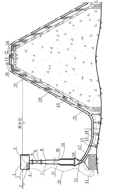
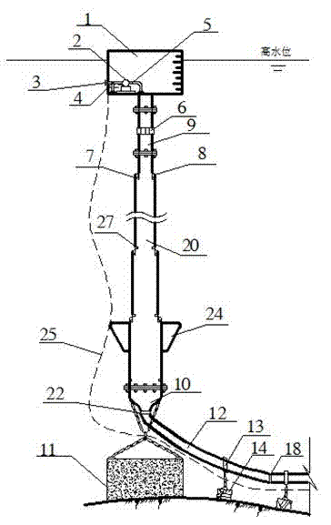
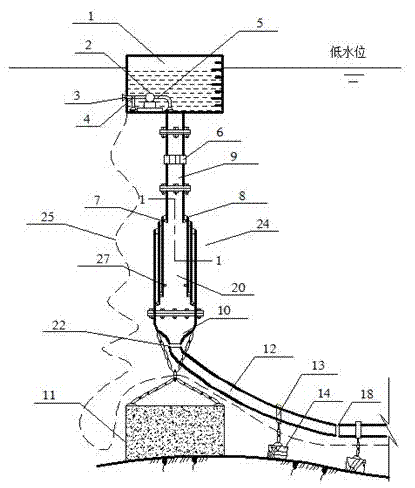
[0034] see figure 1 , figure 1 A schematic diagram of the structure of a hydraulic floating selective water intake device is given. The hydraulic floating selective water intake device adopts the principle of adjusting the height of the water intake based on the self-adjustment of buoyancy and telescopic tubes.

[0035] The hydraulic floating selective water intake device includes a water tank 1, a submersible pump 2 is installed in the water tank 1, the submersible pump 2 is connected to the water outlet pipe 5, and one end of the water outlet pipe 5 is communicated with the water inlet pipe 17 and the common pipe 3 through the electric three-way valve 4 respectively; , one end of the common pipe 3 passes through the side wall of the water tank 1, the water inlet 17' of the water inlet pipe 17 and the water suction port 5' of the other end of the water outlet pipe 5 are suspended, and the position of the water inlet 17' in the water tank 1 is higher than that of the water su...


PUM


Abstract

The invention discloses a hydraulic floating selective water getting device. The device comprises a water tank. A submersible pump is installed in the water tank. The submersible pump is connected to a water outflow pipe. The water outflow pipe is respectively communicated with a water inflow pipe and a shared pipe through an electric three-way valve. A water getting pipe and the bottom of the water tank are connected through a flange. A grate type water getting hole is on the water getting pipe. The bottom of the water getting pipe is connected with an upper flange in the inmost section of atelescopic sleeve. The lower end of the outmost section of the telescopic sleeve is connected with a conical water discharging pipe through a flange. An annular floating box is arranged on the outside diameter of the telescopic sleeve. A suspension ring is arranged on the conical water discharging pipe. The suspension ring is fixed with a concrete anchoring pier through a steel wire rope. The lower end of the water discharging pipe is connected to a metal corrugated pipe and a PE (polyethylene) plastic pipe in sequence through a flange. The PE plastic pipe is arranged at a certain interval with a concrete falling block, and the PE plastic pipe and the concrete falling block are connected with a pipe clamp. The PE plastic pipe is connected with a fixed water conveying pipe on a bank. The fixed water conveying pipe is connected to an interface of a vacuum pump and a vacuum destructor. The device has the advantages of simple structure, convenient installation, flexible water getting height, low installed capacity of assorted power and energy saving. The device is not limited by the water level of a lake reservoir.

Description

technical field [0001] The invention belongs to the technical field of reservoir water intake, in particular to a hydraulic floating selective water intake device with a self-adjusting water tank and a floating sleeve that can be installed in a built reservoir. Background technique [0002] Deep-water lakes are heat-transferred by solar radiation, and the temperature difference in the depth of the lake causes density stratification in the depth of the lake. In late spring, summer and early autumn, the surface water of the lake reservoir is subjected to strong solar radiation and atmospheric heat transfer, and its temperature rises and its density decreases. The positive water body with light lower and heavy layers is stable in stratification; the reverse stratification of lakes and reservoirs is the opposite of the forward stratification, and generally occurs in winter. Unstable layering of heavy and light. [0003] The density and temperature stratification of lakes and r...

Claims


Application Information

Patent Timeline
Patent Type & Authority Patents(China)
IPC IPC(8): E03B3/04
Inventor 卢金锁张博丁艳萍黄廷林
Owner XI'AN UNIVERSITY OF ARCHITECTURE AND TECHNOLOGY
Learn More