

Basin-toilet connecting water-saving pipe
A technology for water-saving pipes and toilets, which is applied to water supply devices, indoor sanitary pipe devices, flushing equipment with water tanks, etc. It can solve the problems of no water-saving devices, etc., and achieve obvious water-saving, simple devices, and easy-to-use effects
Inactive Publication Date: 2011-11-30
郭林德
View PDF0 Cites 2 Cited by
- Summary
- Abstract
- Description
- Claims
- Application Information
AI Technical Summary
Problems solved by technology
[0002] There is no such water-saving device
Method used
View moreImage
Smart ImageViewing Examples


Examples
Embodiment Construction
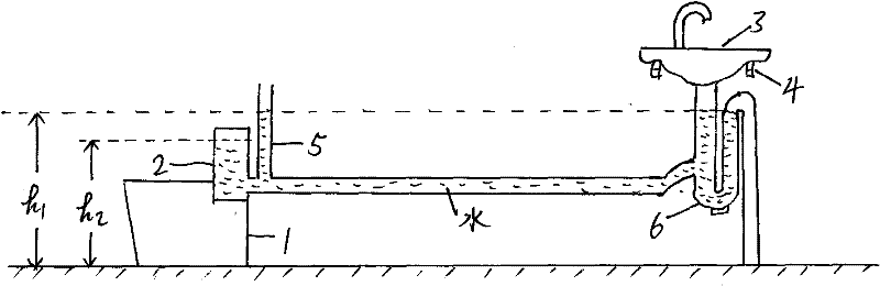
[0008] The toilet water tank, the water level pipe and the curved drainage pipe form a connector. When the washing waste water is discharged from the washbasin, it will automatically flow into the toilet water tank until the water tank is full of water, and the excess waste water is drained away by the drainage curved pipe. When it is seen from the water level pipe that the water in the water tank is insufficient, you can add washing water or tap water from the washbasin.
[0009] h 1 Should be greater than or equal to h 2 , otherwise the toilet tank is full of water.
[0010] The structure of the original toilet remains unchanged, and the operation mode remains unchanged.
Login to View More PUM
 Abstract
This invention is that the water inlet of the toilet tank is communicated with the water outlet of the washbasin. Washing waste water such as washing one's face and hands can automatically flow into the toilet water tank like this, thereby flushing the toilet with waste water, to reach the purpose of saving water. After the washing waste water is discharged from the washbasin, it automatically flows into the toilet water tank until the water tank is full, and the excess waste water is directly discharged to the sewer through the drainage curved pipe under the wash basin. When it is seen from the water level pipe that the water in the toilet tank is insufficient, you can add washing water or tap water from the washbasin. The invention has the advantages of simple device, simple installation, convenient use and obvious water saving. In the accompanying drawings: 1. toilet; 2. toilet water tank; 3. washbasin; 4. washbasin bracket; 5. water level pipe; 6. curved drainage pipe.
Description
Technical field [0001] Flush the toilet with washing waste water such as hair washing, face washing, and hand washing, so as to achieve the purpose of water saving. Background technique [0002] There is no such water-saving device Contents of the invention [0003] The water inlet of the toilet water tank that uses in resident's family now is to be connected on the running water pipe, is to flush the toilet with clean water. The present invention connects the water outlet of the washbasin with the water inlet of the toilet water tank. Washing waste water such as washing one's face and hands can automatically flow into the toilet water tank like this, thereby flushing the toilet with waste water. [0004] The device of the invention is simple, easy to install, easy to use and obvious in water saving. Description of drawings [0005] figure 1 is a schematic diagram of the invention [0006] figure 2 It is a schematic diagram of the drainage curved pipe in the prese...
Claims
Login to View More Application Information
Patent Timeline
 IPC IPC(8): E03C1/14E03D1/00
Inventor 郭林德
Owner 郭林德