A plunger type lubricating grease pump

A lubricating grease and plunger-type technology, which is applied in the direction of lubricating pumps, engine lubrication, engine components, etc., can solve the problems of manual operation safety hazards, incomplete free flow, and affecting project progress, so as to improve work efficiency and save manpower Material effect

Inactive Publication Date: 2011-11-30
TALY AVIATION TECH SHENZHEN
View PDF6 Cites 4 Cited by
  • Summary
  • Abstract
  • Description
  • Claims
  • Application Information

AI Technical Summary

Problems solved by technology

[0003] However, lubricating grease is a fluid with a certain viscosity and consistency, which cannot be completely free-flowing, and air bubbles are inevitably mixed in it, so the lubricating grease pump may inhale part of the gas during the oil suction process; when a certain amount of gas accumulates in the pump cavity Finally, once the plunger moves to the oil suction position in the pump chamber, the air pressure in the pump chamber may be greater than the pressure of the fuel tank and it is difficult to form a negative pressure effect, resulting in an "air lock" phenomenon that prevents the lubricating grease...

Method used


Image

  • A plunger type lubricating grease pump
  • A plunger type lubricating grease pump
  • A plunger type lubricating grease pump

Examples


no. 1 example

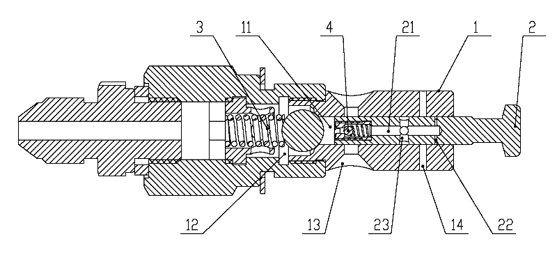
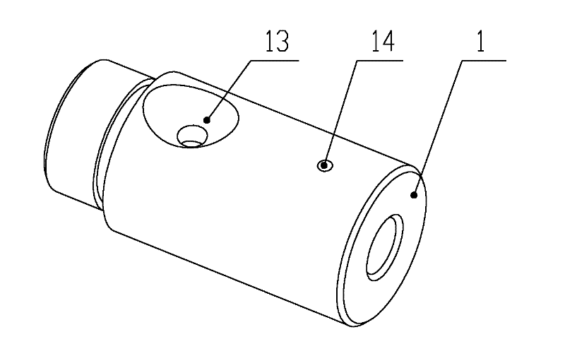
[0029] Please refer to figure 1 with figure 2 The plunger type lubricating grease pump of the present embodiment includes a pump body 1 and a plunger 2. The front end and the middle part of the pump body 1 are respectively provided with an oil outlet 12 and an oil suction hole 13, and the oil outlet 12 and the oil suction hole 13 are used for forming In the pump chamber 11 containing lubricating grease, the plunger 2 is installed at the rear end of the pump body 1. The oil pump end of the plunger 2 is placed in the pump chamber 11, and the other end protrudes out of the pump body 1 for operation, and is operated under the action of external force. reciprocating motion.

[0030] The pump body 1 rear end is also provided with a pump body exhaust hole 14, which can be arranged on the side wall of the pump body 1 rear end, communicates with the inside and outside of the pump body 1, and is located at the opening outside the pump body 1 Together with the oil suction hole 13, it ...

no. 2 example

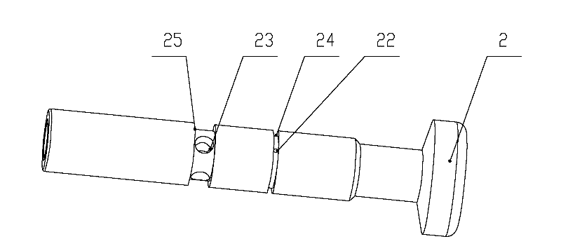
[0038] Please refer to figure 1 with image 3 , the plunger 2 of the plunger type lubricating grease pump of the present embodiment is also provided with a second plunger vent 23, and the second plunger vent 23 is located between the check valve 4 and the first plunger vent 22. Between, when the pump oil end is in the oil suction position and the oil suction port 13 is opened, the second plunger vent hole 23 communicates the plunger chamber 21 with the pump body vent hole 14, and there is a certain pressure in the plunger chamber 21 at this time. The gas will expand, and part of the gas or lubricating grease in the plunger cavity 21 will pass through the second plunger vent hole 23 and the pump body in sequence during the process of communicating the second plunger vent hole 23 with the pump body vent hole 14. The body vent 14 vents outward to the fuel tank.

[0039] In this embodiment, only one set of pump body exhaust holes 14 on the pump body 1 can be provided, and the di...


PUM


Abstract

The invention discloses a plunger-type lubricating grease pump. The plunger-type lubricating grease pump comprise a pump body and a plunger, wherein an oil outlet and an oil sucking hole are formed in the front end and the middle part of the pump body; the plunger is provided with an oil pumping end; the plunger is arranged at the back end of the pump body and the oil pumping end is put into a pump cavity of the pump body; a pump body vent is formed in the back end of the pump body; a plunger cavity and a one-way valve which is used for controlling fluid to flow from the pump cavity to the plunger cavity are arranged in the plunger; and a first plunger vent for communicating the plunger cavity and the pump body vent when the oil pumping end moves to a position between the oil sucking hole and an oil outlet and is a certain distance away from the oil sucking hole is arranged on the plunger. By using pressure difference and combining the compressibility of gas, the plunger-type lubricating grease pump can automatically exhaust the gas accumulated in the pump cavity under a certain condition, so that a gas blockage phenomenon is effectively eliminated, the normal work of a lubricating oil pump is ensured, the working efficiency is obviously improved, and manpower and materials are saved.

Description

technical field [0001] The invention relates to a pump, in particular to a plunger type lubricating grease pump. Background technique [0002] During the working process of the plunger type lubricating grease pump, the plunger can move to the oil suction position in the pump chamber, and the lubricating grease in the oil tank is drawn from the oil suction hole of the pump body into the pump chamber by using negative pressure, and then the plunger flows toward the oil outlet. Move in a straight line in the direction until the limit position of the pump oil, and pump out the lubricating grease from the oil outlet. [0003] However, lubricating grease is a fluid with a certain viscosity and consistency, which cannot be completely free-flowing, and air bubbles are inevitably mixed in it, so the lubricating grease pump may inhale part of the gas during the oil suction process; when a certain amount of gas accumulates in the pump cavity Finally, once the plunger moves to the oil ...

Claims


Application Information

Patent Timeline
IPC IPC(8): F16N13/02
Inventor 刘园侯祖伟顾鹏飞李建国
Owner TALY AVIATION TECH SHENZHEN
Why Eureka
Try Eureka