A kind of interference processing technology of airborne non-vertical dual-antenna interferometric SAR system

A dual-antenna, non-vertical technology, used in radio wave measurement systems, radio wave reflection/re-radiation, utilization of re-radiation, etc., can solve the problems of backwardness, no spaceborne interferometric SAR system, etc., to achieve the effect of promoting development

Active Publication Date: 2011-12-07
CHINA ELECTRONIC TECH GRP CORP NO 38 RES INST
4 Cites 25 Cited by

AI-Extracted Technical Summary

Problems solved by technology

The second is system development. China has always lagged behind foreign countries in the development of space-...

Abstract

The invention relates to an interference processing technology of an airborne non-vertical dual-antenna InSAR system. According to the invention, because airborne double antennas also make back-forth displacements besides left-right placements and up-down placements, a plurality of creative algorithms are provided by taken the above-mentioned situations into consideration, so that problems that precise data and inversion of elevation of the InSAR system can be solved. More particularly, the interference processing technology comprises the following parts that: (1), a local refined registration algorithm is provided, so that a problem that a registration accuracy of main and auxiliary images is difficult to reach a sub pixel level of refined registration can be solved, wherein the problem is caused by pre-and post-arrangements of the antennas; besides, noise is substantially reduced and thus quality of an interference pattern is improved; (2), a plat-earth phase and baseline distance algorithm, wherein the plat-earth phase and baseline distance algorithm are estimated on the basis of inertial navigation data and a main/auxiliary antenna three-dimensional dynamic imaging model, so that a problem that the plat-earth phase is difficult to be eliminated is solved and residual errors of the interferometric phase can be reduced, wherein the problem is caused by an attitude change of a carrier aircraft; (3), an elevation calibration model, which taking a residual phase and a baseline error into consideration, is established; and elevation calibration is completed on the basis of ground control points. According to the invention, airborne non-vertical dual-antenna InSAR system is utilized and a terrain mapping demand is met.

Application Domain

Technology Topic

EngineeringDynamic imaging +7

Image

  • A kind of interference processing technology of airborne non-vertical dual-antenna interferometric SAR system
  • A kind of interference processing technology of airborne non-vertical dual-antenna interferometric SAR system
  • A kind of interference processing technology of airborne non-vertical dual-antenna interferometric SAR system

Examples

  • Experimental program(1)

Example Embodiment

[0049] Hereinafter, the present invention will be further implemented in conjunction with the drawings.
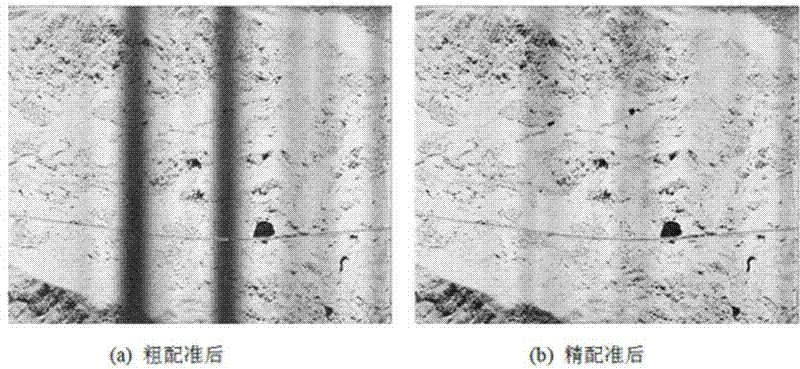
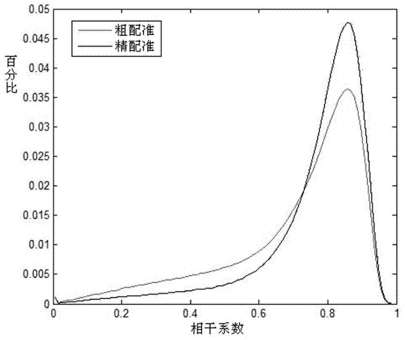
[0050] For airborne dual-antenna interferometric SAR, after a simple translation of the main and auxiliary images, coarse registration accuracy can be achieved. image 3 (a) is the coherence coefficient map of the main and auxiliary images after rough registration. From the figure, we can see that there are many low-coherence areas along the azimuth direction. These areas correspond exactly to the moments when the parameters in the aircraft inertial navigation data change suddenly.
[0051] After coarse registration, the overall deviation of the main and auxiliary images is about 1 pixel, and the local area (mainly at different azimuth times) causes a large registration deviation due to aircraft shake. Therefore, at this time, the registration parameters need to be accurately estimated in the local area. According to the local fine registration algorithm, 16*16 grid points are selected, and we get the result after fine registration (such as image 3 (b)). Figure 4 Gives the azimuth offset parameter on the grid point, Figure 5 The histogram comparison of coherence coefficient before and after fine registration is given.
[0052] The height function H_sensor(t), roll angle function angle_r(t), pitch angle function angle_p(t) and yaw angle function angle_h(t) of antenna A are as follows Image 6 Shown. Using the flat-ground phase estimation algorithm, the flat-ground phase can be obtained.
[0053] After flattening, phase filtering, phase unwrapping, and phase-to-elevation processing, uncalibrated elevation data is obtained, such as Figure 7 Shown.
[0054] We chose as Figure 8 The area shown is height corrected. According to the correction model in this article, we selected 4 control points and 1 commanding height evenly distributed on flat ground, and used them to calculate the model parameters. At the same time, the remaining points are used to verify the accuracy of elevation correction. As shown in Table 1.
[0055] From the error result, the method of the present invention can effectively achieve the purpose of high-precision DEM inversion.
[0056] Table 1 Error analysis of ground control points (unit: m)
[0057]

PUM

no PUM

Description & Claims & Application Information

We can also present the details of the Description, Claims and Application information to help users get a comprehensive understanding of the technical details of the patent, such as background art, summary of invention, brief description of drawings, description of embodiments, and other original content. On the other hand, users can also determine the specific scope of protection of the technology through the list of claims; as well as understand the changes in the life cycle of the technology with the presentation of the patent timeline. Login to view more.

Similar technology patents

Classification and recommendation of technical efficacy words

Why Eureka
Try Eureka