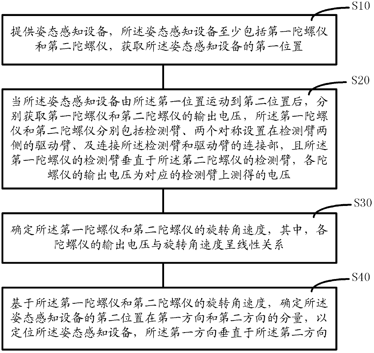
Positioning method for posture sensing equipment and control method for mouse pointer
A technology of attitude perception and positioning method, which is applied in the input/output process of data processing, instruments, electrical digital data processing, etc. The effect of fast 3D positioning, improved sensitivity, and fast 2D positioning
- Summary
- Abstract
- Description
- Claims
- Application Information
AI Technical Summary
Problems solved by technology
Method used
Image
Examples
no. 1 example
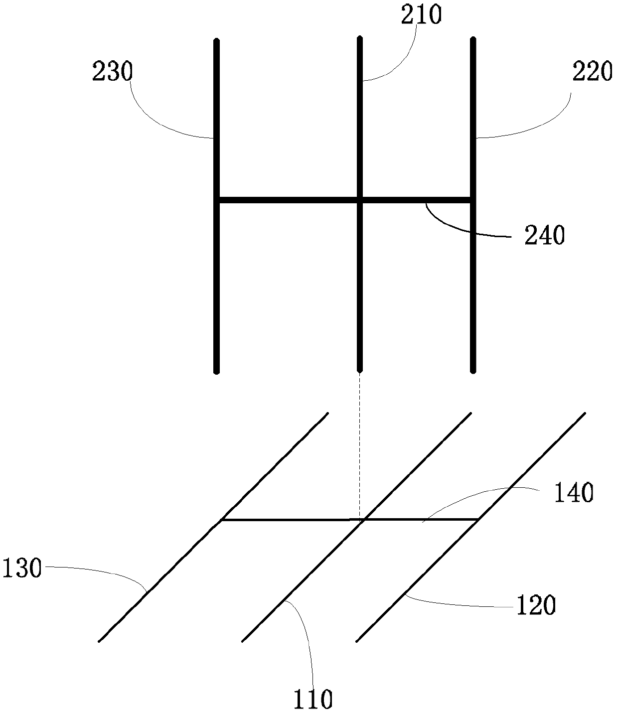
[0072] Please refer to figure 2 , in the first embodiment of the present invention, firstly, an attitude sensing device including at least a first gyroscope and a second gyroscope is provided, wherein:
[0073] The first gyroscope includes: a detection arm 110; a driving arm 120 and a driving arm 130 symmetrically located on both sides of the detection arm 110; connecting the center of the detection arm 110, the center of the driving arm 120 and the driving arm 130 The connecting part 140 of the center;
[0074] The second gyroscope includes: a detection arm 210; a driving arm 220 and a driving arm 230 symmetrically located on both sides of the detection arm 210; connecting the center of the detection arm 210, the center of the driving arm 220 and the driving the connecting portion 240 at the center of the arm 230;
[0075] And the detection arm 110 of the first gyroscope is perpendicular to the detection arm 210 of the second gyroscope.
[0076] The first gyroscope and th...
no. 2 example
[0112] In an embodiment of the present invention, a method for controlling a mouse pointer is provided.
[0113] In the second embodiment of the present invention, the movement of the mouse pointer is controlled by a space mouse. By moving the space mouse, the position of the space mouse is mapped to the mouse pointer on the display screen, so as to control the movement of the mouse pointer on the display screen. The space mouse includes such as figure 2 The first and second gyroscopes are shown.
[0114] Wherein, the first gyroscope includes a detection arm 110, a drive arm 120 symmetrically located on both sides of the detection arm 110, and a drive arm 130 connecting the center of the detection arm 110, the center of the drive arm 120, and the center of the drive arm 130. The connecting part 140; the second gyroscope includes a detection arm 210; a driving arm 220 and a driving arm 230 symmetrically located on both sides of the detection arm 210; connecting the center of...
no. 3 example
[0137] Different from the first embodiment, in order to realize the three-dimensional positioning of the gesture-aware device, please refer to Figure 10 , the gesture sensing device according to the third embodiment of the present invention further includes a third gyroscope. The third gyroscope includes a detection arm 910; a driving arm 920 and a driving arm 930 symmetrically located on both sides of the detection arm 910; connecting the center of the detection arm 910, the center of the driving arm 920 and the center of the driving arm 930 The connection part 940.
[0138] In an embodiment of the present invention, the third gyroscope is a single-axis gyroscope, and the material of the third gyroscope is crystal.
[0139] Please refer to Figure 11 , Figure 11 In the gesture sensing device, the positional relationship between the first gyroscope, the second gyroscope and the third gyroscope is shown, the detection arm 110 of the first gyroscope, the detection arm 210 of ...
PUM
 Abstract
Description
Claims
Application Information
 - R&D
- Intellectual Property
- Life Sciences
- Materials
- Tech Scout
- Unparalleled Data Quality
- Higher Quality Content
- 60% Fewer Hallucinations
Browse by: Latest US Patents, China's latest patents, Technical Efficacy Thesaurus, Application Domain, Technology Topic, Popular Technical Reports.
© 2025 PatSnap. All rights reserved.Legal|Privacy policy|Modern Slavery Act Transparency Statement|Sitemap|About US| Contact US: help@patsnap.com


