Coil winding device

A winding device and wire technology, which is applied to electromechanical devices, manufacturing motor generators, electrical components, etc., can solve the problems of large-scale, complex and large-scale main center body 211, and achieve easy and simplified assembly and adjustment. Construct, reduce the number of effects

Active Publication Date: 2013-11-20
NITTOKU ENG CO LTD
View PDF1 Cites 0 Cited by
  • Summary
  • Abstract
  • Description
  • Claims
  • Application Information

AI Technical Summary

Problems solved by technology

There is thus the problem that these motors 217, 218, 219 must always be driven at the same time when winding, so their control becomes more complicated
Therefore, there is a problem that the structure of the main center body 211 is complicated and the size of the main center body 211 is enlarged.
That is, in the conventional structure using the joint member 214, there is a problem that independent movement of a plurality of divided pieces constituting the guide member 206 will lead to a more complicated structure and an increase in size, and as a result, the winding device 200 obtained The unit price has risen significantly

Method used


Image

  • Coil winding device
  • Coil winding device
  • Coil winding device

Examples


Embodiment Construction

[0038] Next, the best mode for carrying out the present invention will be described with reference to the drawings.

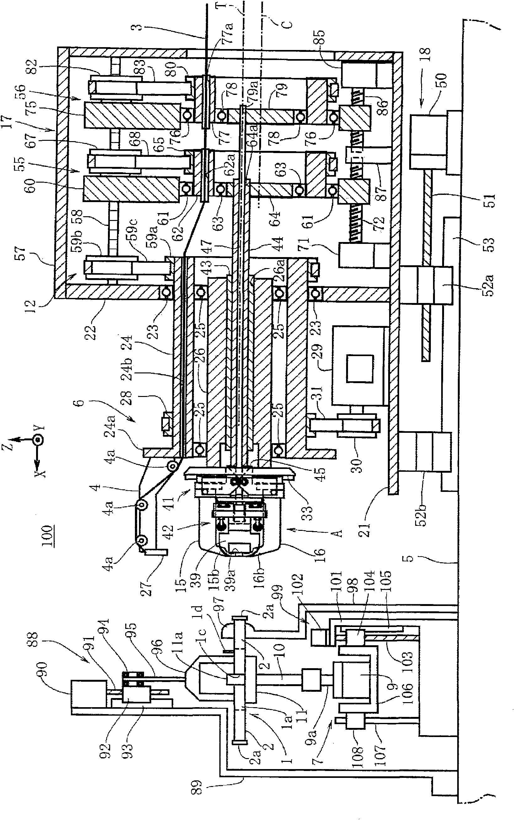
[0039] figure 1 Shown is the winding device 100 of the present invention. This winding device 100 is a device that uses a plurality of magnetic poles 2 constituting a multi-pole armature 1 of a generator or motor as a winding core, and winds a multilayer wire 3 around the magnetic poles 2 as the winding core. That is, it is a flyer-type winding device 100 that performs winding using the flyer 4 that rotates around the magnetic pole 2 while drawing out the wire 3 . The multi-pole armature 1 in the present embodiment is formed to include an annular portion 1 a and 18 magnetic poles 2 protruding radially outward from the annular portion 1 a ( Figure 6 Indicates 7 poles). like Figure 6 As shown, slots 1 b are formed between the magnetic poles 2 in the multi-pole armature 1 . The cross-section of the magnetic pole 2 as a winding core is quadrangular, and the...


PUM


Abstract

The invention provides a coil winding device capable of reducing the number of components and low in price, which comprises a spindle (24) with a rotary shaft (T) of a flying fork (4) as the rotation center thereof; a motor (29) for enabling the spindle (24) to rotate together with the flying fork (4); a guide member (15,16,39,39) a countershaft (62,67) parallel to the rotary shaft (T) with a center shaft (C) offset from the rotary shaft (T) as the rotation center thereof; a central body (64,79) arranged on the countershaft in a free rotation manner; a rod (44,47) passing through the spindle (24). One end of the rod is arranged or clamped with the guide member and the other end of the rod offsetting from the center shaft (C) is fixed to the central body; and a rotation transfer mechanism (12) for transferring the rotation of the spindle to the countershaft, so that the countershaft can rotate synchronously.

Description

technical field [0001] The present invention relates to a flyer type winding device for winding a multi-pole armature of a motor or the like. More specifically, it relates to a flyer type winding device having a guide member for guiding a wire to a slot or the like of a multi-pole armature. Background technique [0002] Conventionally, in order to wind the wire for forming the coil on the magnetic poles of a multi-pole armature, a flyer-type winding device having a flyer that draws out the wire while rotating around the magnetic poles and winds the wires around the magnetic poles has been widely used. wire. In addition, the flyer-type winding device is provided with a guide member for guiding the wire drawn out from the rotating flyer with respect to the magnetic poles of the winding core, which is a multi-pole armature at a fixed position. Since the guide member guides the wire with respect to the fixed magnetic pole, it needs to be held in a stationary state with respect...

Claims


Application Information

Patent Timeline
Patent Type & Authority Patents(China)
IPC IPC(8): H02K15/095
Inventor 酒井勉
Owner NITTOKU ENG CO LTD
Why Eureka
Try Eureka