
occupant restraint device

A technology of occupant restraint and equipment, applied in pedestrian/occupant safety arrangement, vehicle safety arrangement, transportation and packaging, etc., can solve the problems of neck torque and neck pressure

Inactive Publication Date: 2011-12-07
JOYSON SAFETY SYST GERMANY GMBH
View PDF6 Cites 7 Cited by
  • Summary
  • Abstract
  • Description
  • Claims
  • Application Information

AI Technical Summary

Problems solved by technology

This results in neck moments and excessive neck pressure

Method used


Image

  • occupant restraint device
  • occupant restraint device
  • occupant restraint device

Examples


Embodiment Construction

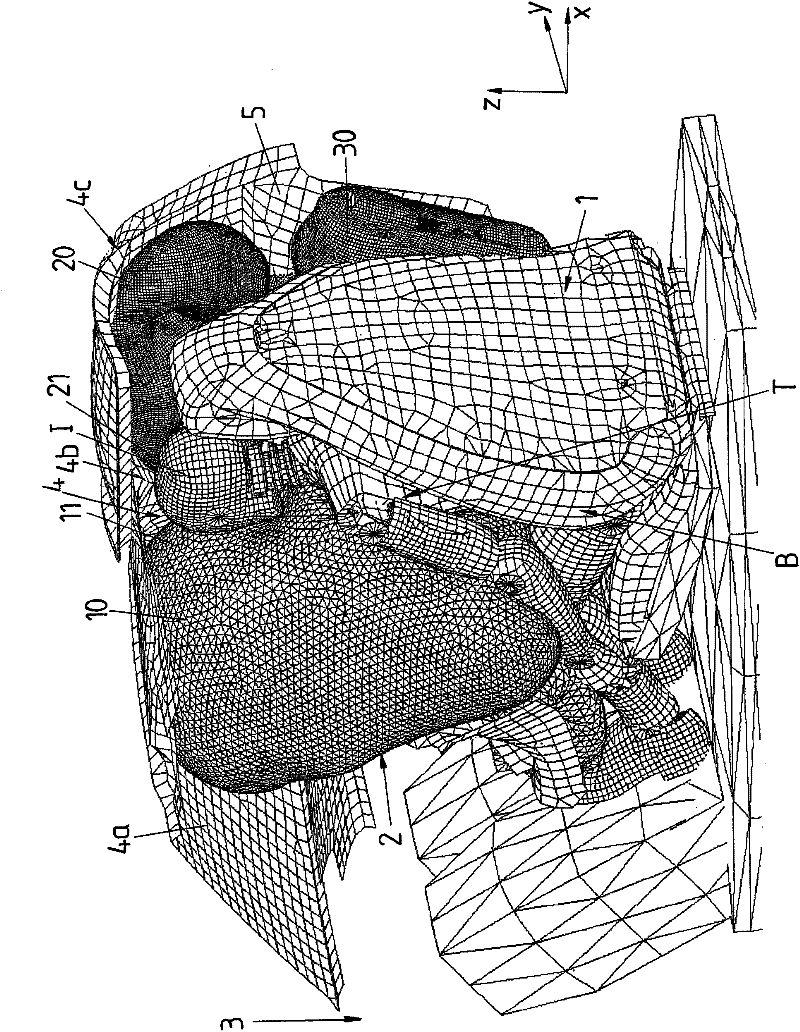
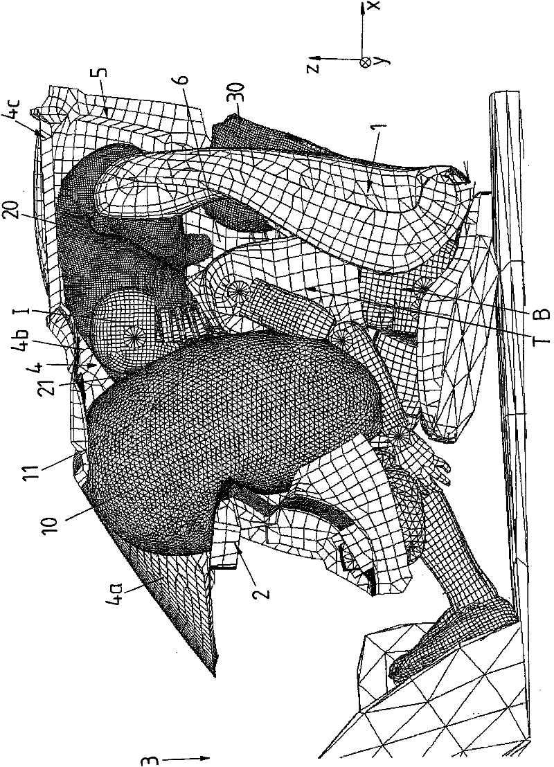
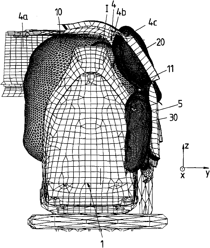
[0021] figure 1 versus Figure 2 to Figure 4 The combination of shows a perspective view of the occupant restraint device 1 according to the present invention.

[0022] Figure 1 to Figure 4 An occupant I is shown, the occupant I is expected to occupy the seat 1 in the form of a front passenger seat, so that the motor vehicle door 5 is continuous along the transverse axis y of the motor vehicle adjacent to the occupant I along the xz plane, and the A pillar 4 is adjacent to the occupant I along the vehicle longitudinal axis x, wherein the A-pillar is arranged in front of the occupant I along the vehicle longitudinal axis x. The front windshield 4a is adjacent to the A-pillar 4 along the vehicle transverse axis y, wherein the windshield faces the occupant I along the vehicle longitudinal axis x. The roof spar 4c is along the vehicle longitudinal axis x from the upper end 4b of the A-pillar (turned relative to the vertical axle z), wherein the roof spar is continuous above the mo...


PUM


Abstract

The invention relates to an occupant restraint device for a motor vehicle comprising: a first airbag (10) inflatable with gas to protect an occupant (I) expected to occupy a maneuver A seat (1) of a vehicle in the form of a driver's seat or a front passenger seat, wherein a first airbag (10) is designed to be arranged in a non-inflated state in a steering wheel (2) of a motor vehicle; and a second airbag (20), the second airbag (20) can be inflated with gas to protect the occupant (I). According to the invention, the second airbag (20) is designed such that its edge region (21) facing the vehicle front (3) extends along the A-pillar (4) of the motor vehicle in the inflated state.

Description

Technical field [0001] The invention relates to an occupant restraint device for a motor vehicle according to the preamble of claim 1 and a method for triggering such an occupant restraint device. Background technique [0002] Such an occupant restraint device generally includes: a first airbag that can be inflated with gas to protect an occupant who is expected to occupy a seat in the form of a driver's seat or a front passenger seat of a motor vehicle, wherein the first airbag An airbag is arranged in a non-expanded state and arranged to be arranged in a steering wheel or dashboard of a motor vehicle; and a second airbag that can be inflated with gas to protect the occupant. [0003] In a frontal / angled impact, there is a danger that the head of the occupant to be protected collides with the A-pillar in a triangular area where the A-pillar, windshield and roof frame abut each other, especially if the A-pillar Extends very far in the direction of the occupant. This leads to exce...

Claims


Application Information

Patent Timeline
Patent Type & Authority Applications(China)
IPC IPC(8): B60R21/231
CPCB60R2021/0004B60R21/231B60R2021/0072B60R2021/0009B60R2021/23107
Inventor 奥拉夫·科莫尔雷纳·霍伊施米德马蒂亚斯·格鲁贝
Owner JOYSON SAFETY SYST GERMANY GMBH
Learn More