Vortex pump impeller with groove structure

A swirl pump and impeller technology, which is applied to parts, pumps, and pump components of elastic fluid pumping devices, can solve the problems of swirl pump lift, low efficiency, and hydraulic loss, and achieve lifting without overload performance, weight reduction, and shaft power reduction

Pending Publication Date: 2020-06-26
JIANGSU UNIV ZHENJIANG RES INST OF FLUID ENG EQUIP TECH +1
View PDF2 Cites 3 Cited by
  • Summary
  • Abstract
  • Description
  • Claims
  • Application Information

AI Technical Summary

Problems solved by technology

[0003] The swirl pump is a non-clogging pump suitable for conveying mixed media, but the traditional swirl pump also has certain shortcomings. Due

Method used


Image

  • Vortex pump impeller with groove structure
  • Vortex pump impeller with groove structure
  • Vortex pump impeller with groove structure

Examples


Embodiment

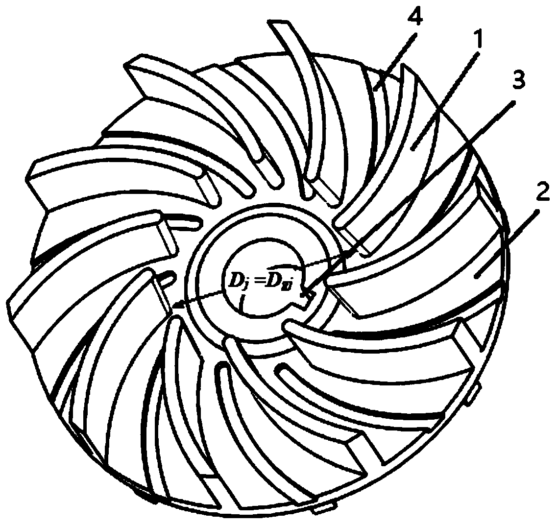
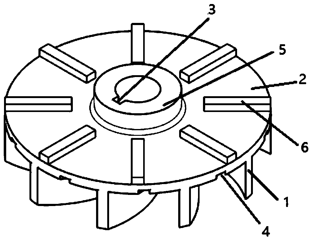
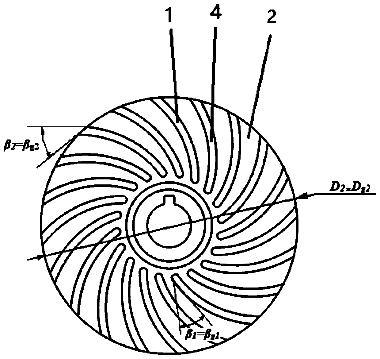
[0048] combine Figure 1-Figure 4 , the embodiment of the present invention discloses a swirl pump impeller with a groove structure, the impeller includes an impeller blade 1, a rear cover plate 2, a hub 5 and a back blade 6, and the impeller blade 1 is located on the rear cover plate 2, the back blade 6 is located on the other side of the rear cover 2, and the rear cover 2 is provided with a groove, and the groove is arranged in the blade flow channel between the impeller blades In the middle, the groove is consistent with the shape of the blade. The hub 5 is located at the center of the rear cover 2 , and the sidewall of the hub has a keyway 3 .

[0049] In this embodiment, the shape of the groove is consistent with the shape of the vane, and it is located in the middle of the flow path of the impeller. This structure can strengthen the confinement ability of the impeller to the fluid and improve the pumping capacity.

[0050] In some embodiments, the geometric parameters ...


PUM


Abstract

The invention provides a vortex pump impeller with a groove structure. The impeller comprises impeller blades, a rear cover plate, a hub and back blades, wherein the impeller blades are located on oneside of the rear cover plate, the back blades are located on the other side of the rear cover plate, grooves are formed in the rear cover plate, each groove is formed in the middle of a blade passageway between every two impeller blades, and the grooves are consistent with the blades in shape. The vortex pump impeller has good hydraulic performance, and the grooves are additionally formed in therear cover plate, so that the constraint of the impeller on fluid is enhanced, and losses are reduced.

Description

technical field [0001] The invention relates to the field of impellers, in particular to a swirl pump impeller with a groove structure. Background technique [0002] The swirl pump belongs to the non-clogging pump. It is a multiphase flow pump named because of the swirling vortex motion in the internal flow. It is mostly used for pumping complex media. The non-clogging characteristics of swirl pumps make them widely used in sewage treatment, paper making, chemical and pharmaceutical industries. The impeller of the swirl pump is open or semi-open. The impeller is biased to the side of the pump chamber or completely retracted to the back cavity of the pump casing. Two different impeller arrangements form two design concepts of the swirl pump. Two different The arrangement is a trade-off between pumpability and non-clog performance. When the swirl pump is working, a through-flow is generated at the outlet of the impeller due to centrifugal force, and a medium exchange occurs ...

Claims


Application Information

Patent Timeline
IPC IPC(8): F04D29/22F04D29/66
CPCF04D29/2272F04D29/2288F04D29/669
Inventor 高雄发施卫东施亚张德胜赵婷郎涛
Owner JIANGSU UNIV ZHENJIANG RES INST OF FLUID ENG EQUIP TECH
Why Eureka
Try Eureka