Receiver system, its arrangement method and positioning system comprising the receiver system

A receiver and receiving node technology, applied in the field of positioning systems, can solve problems such as difficult practical application, complex coordination mechanism, inflexible structure, etc., to achieve effective coordination, reduce calibration workload, and flexible structure

Inactive Publication Date: 2011-12-14
NEC (CHINA) CO LTD
View PDF2 Cites 1 Cited by
  • Summary
  • Abstract
  • Description
  • Claims
  • Application Information

AI Technical Summary

Problems solved by technology

[0013] However, the structure of the above-mentioned LTS system is very inflexible and the coordination mechanism is complicated, so it is difficult to put into practical application

Method used


Image

  • Receiver system, its arrangement method and positioning system comprising the receiver system
  • Receiver system, its arrangement method and positioning system comprising the receiver system
  • Receiver system, its arrangement method and positioning system comprising the receiver system

Examples


Embodiment Construction

[0039] Hereinafter, a receiver system for positioning, a method for arranging the receiver system, and a positioning system including the receiver system provided by the present invention will be described in detail through embodiments with reference to the accompanying drawings.

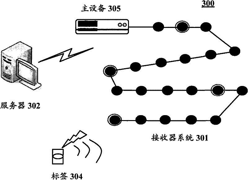
[0040] First, refer to image 3 The positioning system according to the present invention will be described. image 3 A system architecture diagram of a positioning system according to an embodiment of the present invention is shown.

[0041] Such as image 3 As shown, a system according to the present invention may include a receiver system 301 , a server 302 , a tag device 304 and a master device 305 . Wherein, the receiver system 301 includes a plurality of receiving nodes, which can be installed on the ceiling of a room, for example. The receiver system 301 is used for receiving ranging signals, such as ultrasonic signals, transmitted by the tag device 304 to detect TOA data. The master devi...


PUM


Abstract

The present application discloses a receiver system for positioning, a method for arranging the receiver system, and a positioning system comprising the receiver system. The receiver system may comprise a group of nodes, the group of nodes comprising receive nodes for receiving a ranging signal. In this group of nodes, the receive nodes may be arranged according to a predetermined mode. Further, the group of nodes may comprise a reference node, and locations of other receive nodes within this group of nodes may be determined based on information on the predetermined mode and location of the reference node. With the present invention, the receiver system may have a more flexible structure, which may be better adapted to complex situations in practical application. At the same time, the calibration workload in a complex application situation can be significantly reduced.

Description

technical field [0001] The present invention relates to positioning technology, and more particularly to a receiver system for positioning, a method for arranging the receiver system and a positioning system comprising the receiver system. Background technique [0002] In a ubiquitous computing environment, a location tracking system (LTS) is required to provide location services in order to enhance existing applications and support new applications. Currently, there is an increasing demand for highly accurate tracking of people and objects in many applications such as warehouses, mines, subways, smart buildings, healthcare, and restaurants. [0003] For example, in a warehouse, real-time tracking of the exact location of goods is required for efficient management of goods. Typical examples can include tracking of steel goods in steel mills, commodity tracking in retail warehouses, etc. Especially for goods that are sensitive or even dangerous to people, it is more necessa...

Claims


Application Information

Patent Timeline
Patent Type & Authority Applications(China)
IPC IPC(8): G01S5/00G01S5/14G01S5/30G01S5/12G01S15/74
CPCG01S5/18G01S11/16G01S5/186G01S5/30
Inventor 赵军辉杉山高弘
Owner NEC (CHINA) CO LTD
Why Eureka
Try Eureka