Method for precisely locating laser beam space

A laser beam and precise positioning technology, applied in optics, optical components, installation, etc., can solve the problems of high experience requirements for debugging personnel, unsuitability of complex optical systems, and low work efficiency

Active Publication Date: 2011-12-14
THE FIRST RES INST OF MIN OF PUBLIC SECURITY +1
View PDF2 Cites 2 Cited by
  • Summary
  • Abstract
  • Description
  • Claims
  • Application Information

AI Technical Summary

Problems solved by technology

The disadvantage of this method is that the position adjustment from the millimeter level needs to be adjusted repeatedly to achieve position accuracy, so the wo

Method used


Image

  • Method for precisely locating laser beam space
  • Method for precisely locating laser beam space
  • Method for precisely locating laser beam space

Examples


Embodiment Construction

[0015] The technical solutions of the present invention will be described in further detail below in conjunction with the accompanying drawings and specific embodiments.

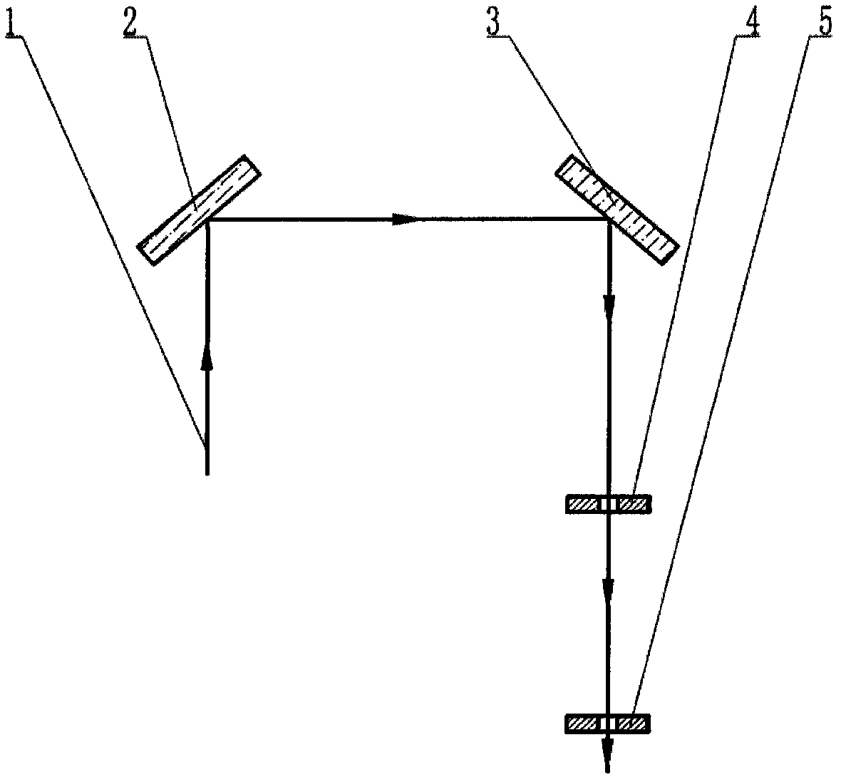
[0016] Such as figure 1 as shown, figure 1 It is a basic principle diagram of a single laser beam spatially precise positioning method of a laser beam spatially precise positioning method of the present invention. The laser beam 1 is adjusted in space by the rotation and pitch of the mirror 2 and the mirror 3 so that the light 1 passes through the holes of the tooling 4 and the tooling 5, and a straight line is determined according to the two points, and a single laser beam can be positioned.

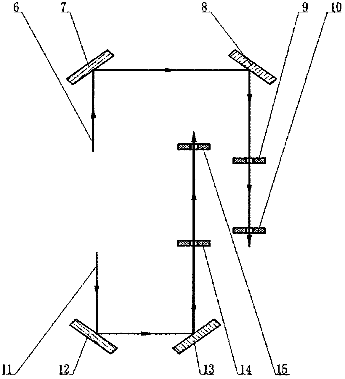
[0017] Such as figure 2 as shown, figure 2 It is a basic principle diagram of a method for spatially precise positioning of laser beams according to the present invention, a method for spatially precise positioning of multiple laser beams. Taking two parallel laser beams as an example, firstly, the laser beam 6 ...


PUM


Abstract

The invention relates to a method for precisely locating a laser beam space, wherein at least one laser beam is incident to a first reflector; the first reflector reflects the laser beam to a second reflector; the second reflector reflects the reflected laser beam; therefore, the laser beam reflected by the second reflector passes through a tooling hole in a corresponding tooling set; the preciselocation of the laser beam is realized; the number of the laser beams is same as the number of the tooling sets; the tooling set comprises a first tooling and a second tooling; the hole centre of thefirst tooling and the hole centre of the second tooling are on the same straight line; and the straight line is vertical to the hole bottom surface of the first tooling.

Description

technical field [0001] The invention relates to the field of spatial form adjustment of laser beams, in particular to a method for spatially precise positioning of laser beams. Background technique [0002] For the debugging of complex optical systems with a long optical path that requires a positioning accuracy of 100 microns or even tens of microns, it is usually required to improve the processing accuracy and higher geometric tolerance requirements to ensure the accuracy of the position of the beam passing through. The higher requirements are generally in the Adding several fine-tunable mechanisms in the reflection or refraction light path, and adjusting these mechanisms to determine the beam position, this method belongs to the open-loop adjustment method. The disadvantage of this method is that the position adjustment from the millimeter level requires repeated adjustments to achieve position accuracy, which has low work efficiency and requires high experience for debug...

Claims


Application Information

Patent Timeline
IPC IPC(8): G02B7/182G02B7/02
Inventor 王守山许正光陈惠民庞晓东高宁孙丹常海龙范志永崔海涛霍梅春
Owner THE FIRST RES INST OF MIN OF PUBLIC SECURITY
Why Eureka
Try Eureka