Static iron core and its assembly method

An assembly method and technology of static iron core, applied in the direction of sounding equipment, instruments, sensors, etc., can solve the problems of large tolerance range, small deformation size of riveted rear face, change of air gap, etc., to achieve stability and consistency guarantee, stability The effect of good stability and consistency, and increased air gap accuracy

Inactive Publication Date: 2011-12-14
BEIQI FOTON MOTOR CO LTD
View PDF6 Cites 2 Cited by
  • Summary
  • Abstract
  • Description
  • Claims
  • Application Information

AI Technical Summary

Problems solved by technology

[0003] The static iron core of the original product, because the end diameter of the riveted surface is only 8mm, and the end surface height is only 1.2mm, limited by the size of the end surface, when it is fixed to the horn base, only the pressure riveting process can be used. When riveting, the end surface The force-bearing surface is small, coupled with the influence of uniform force on the riveted end surface, so the riveted end surface and the speaker back shell are in full 360° contact and fixed surface to surface, and the riveted end surface is small in deformation size, which will inevitably bring the following disadvantages: 1. 1. The accuracy of the air gap is low, and the tolerance range is relatively large, usually up to 0.4mm; 2. Manual adjustment is required; 3. It is easy to loosen during the vibration of the speaker, which will cause the air gap to change and generate noise

Method used


Image

  • Static iron core and its assembly method
  • Static iron core and its assembly method
  • Static iron core and its assembly method

Examples


Embodiment Construction

[0016] The present invention will be described in further detail below in conjunction with specific embodiments and the accompanying drawings shown therein. In the following embodiments of the present invention, the static iron core of the electric car horn is taken as an example for illustration, but the present invention is not limited to these embodiments.

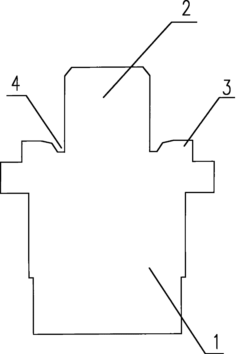
[0017] refer to figure 1 , which is a schematic longitudinal section of the static iron core of the present invention. The static iron core is a static iron core for an automobile electric horn, and it includes an iron core body 1 and a stud 2, and the stud 2 is positioned at one end of the iron core body 1, from which figure 1 It can be clearly seen that the stud 2 is formed at the central position of one end face of the iron core body 1, and there is a riveting part 3 on the outer edge of the stud 2, and the static iron core and the speaker base (not shown) are connected through the riveting part 3 achieve fixation....


PUM


Abstract

The invention discloses a static iron core. The static iron core is used for an electric horn, a stud is arranged in a center position at one end of the static iron core, a riveting part for fixation with a horn base is arranged on the end face of the static iron core and is located at the outer edge of the stud, and a groove is formed between the end face of the riveting part and the stud, so that the riveting part takes a shape of a continuous annular lug boss surrounding the stud. When the static iron core and the horn base are fixed, a riveting process can be adopted to fix the riveting part in the static iron core and the horn base, so that air gap precision between the riveting part and the horn base is greatly increased; a manual regulation procedure is not needed after machining is completed; and in a horn working process, the iron core is firm in fixation, so that an air gap value is always kept in a factory setting state, and the stability and the consistence of the horn arebetter guaranteed.

Description

technical field [0001] The invention relates to the technical field of electric horn air gap adjustment, relates to a static iron core and an assembly method thereof, in particular to a static iron core for an electric horn and an assembly method thereof. Background technique [0002] Electric horns (such as automobile electric horns) are used to warn pedestrians and other vehicles to attract attention and ensure driving safety. The pitch of the electric horn is related to the air gap of the iron core. When the air gap of the iron core is small, the vibration frequency of the diaphragm is high (that is, the pitch is high); and when the air gap of the iron core is large, the vibration frequency of the diaphragm is low (that is, the pitch is low). . [0003] The static iron core of the original product, because the end diameter of the riveted surface is only 8mm, and the end surface height is only 1.2mm, limited by the size of the end surface, when it is fixed to the horn bas...

Claims


Application Information

Patent Timeline
Patent Type & Authority Applications(China)
IPC IPC(8): G10K9/13H04R11/02
Inventor 周娟石丽华孙雪梅岳本龙
Owner BEIQI FOTON MOTOR CO LTD
Why Eureka
Try Eureka