
An electric operating mechanism for a high-voltage isolating switch and an earthing switch

A technology of electric operating mechanism and high-voltage isolation switch, which is applied to contact drive mechanism, power device inside the switch, etc., and can solve the problems of insufficiency, loud noise, damage to components, etc.

Inactive Publication Date: 2011-12-14
沈国祥
View PDF7 Cites 0 Cited by
  • Summary
  • Abstract
  • Description
  • Claims
  • Application Information

AI Technical Summary

Problems solved by technology

The electric operating mechanisms of these two structures are fast and impactful. Even if there is a buffer device, it is easy to cause damage to the components due to impact, and even cause the switch to be opened, closed or not in place. At the same time, there are requirements for motor power. Large, there are disadvantages such as high noise and large volume

Method used


Image

  • An electric operating mechanism for a high-voltage isolating switch and an earthing switch
  • An electric operating mechanism for a high-voltage isolating switch and an earthing switch
  • An electric operating mechanism for a high-voltage isolating switch and an earthing switch

Examples


Embodiment Construction

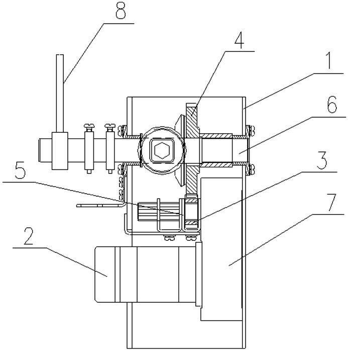
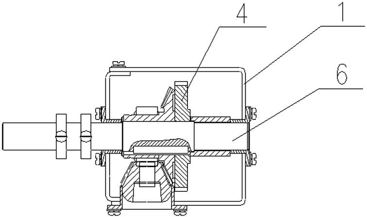
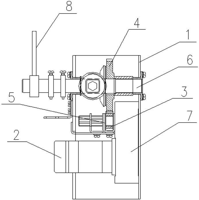
[0010] Such as figure 1 As shown, the electric operating mechanism of the high-voltage isolating switch and the grounding switch includes a fixed frame body 1, and the motor 2 is fixedly connected to the lower part of the fixed frame body 1, and the output end of the motor 2 is connected to the reduction box 7, and on the output shaft of the reduction box 7 Connect the driving pinion 3, set the main shaft 6 of the operating mechanism on the upper part of the fixed frame body 1, set the driven gear 4 that cooperates with the driving pinion 3 on the main shaft 6 of the operating mechanism, and set the fork device on the output shaft of the reduction box 7 5. The driving pinion 3 is set in the shift fork device 5 . An output crank arm 8 is arranged on the operating mechanism main shaft 6 .


PUM


Abstract

An electric operating mechanism for a high-voltage isolating switch and a grounding switch relates to the technical field of electric operating mechanisms for switches. Including the fixed frame, the motor is fixedly connected to the lower part of the fixed frame, the gear box is connected to the output end of the motor, the driving pinion is connected to the output shaft of the gear box, the main shaft of the operating mechanism is set on the upper part of the fixed frame, and the main shaft of the operating mechanism A driven bull gear cooperating with the driving pinion is arranged on the top, a shift fork device is arranged on the output shaft of the reduction box, and the driving pinion is arranged in the shift fork device. The spindle has low speed, no inertia, no buffer device, simple structure and more reliable action. Compared with the original electric mechanism, the power required to operate the same isolating switch is greatly reduced.

Description

technical field [0001] The invention relates to the technical field of an electric operating mechanism of a switch. Background technique [0002] At present, the transmission of the existing electric operating mechanism is directly transmitted to the main shaft of the operating mechanism through the motor through the worm gear reduction device after deceleration, and the main shaft of the operating mechanism is directly transmitted to the main shaft of the isolation switch through the crank arm, and is set on the electric operating mechanism. Buffer. Or directly connect with the isolating switch and the main shaft of the grounding switch. The electric operating mechanisms of these two structures are fast and impactful. Even if there is a buffer device, it is easy to cause damage to the components due to impact, and even cause the switch to be opened, closed or not in place. At the same time, there are requirements for motor power. Large, there are disadvantages such as hig...

Claims


Application Information

Patent Timeline
Patent Type & Authority Applications(China)
IPC IPC(8): H01H3/32H01H3/26
Inventor 沈国祥
Owner 沈国祥
Learn More