
Plastic Bottle Mouth Rotary Cutting Machine

A technology of rotary cutting machine and plastic bottle, which is applied in the field of plastic bottle neck rotary cutting machine, which can solve the problems of normal operation of automatic blow molding machine, unreasonable price of automatic blow molding machine, high labor intensity of workers, etc. problem, to achieve the effect of overcoming labor intensity, improving resection efficiency, and convenient operation

Inactive Publication Date: 2011-12-21
SUZHOU TONGDA MOLD
View PDF4 Cites 7 Cited by
  • Summary
  • Abstract
  • Description
  • Claims
  • Application Information

AI Technical Summary

Problems solved by technology

[0002] As is well known in the industry, automatic blow molding machines can efficiently blow products such as baby bottles, beverage bottles, cosmetic bottles, pharmaceutical liquid bottles and various Condiment bottles, but because of the process, there are flashes on the mouth of the bottle after blowing. The flashes are also known as process scraps. They need to be cut off before they can be put on the market as qualified products.
[0003] At present, there are two ways to remove the flash of the bottle mouth. One is to use manual removal. Large and irregular incision; the second is to cut off the mouth of the bottle by carrying it on the automatic blow molding blow molding machine, typical as the "cutting mouth of the automatic blow molding blow molding machine" respectively disclosed in the invention patent application publication number CN1654189A and US3886824 mechanism" and "blowing method and device for hollow plastic containers"
However, although many shortcomings of manual work can be avoided by matching the bottle cutting mechanism on the automatic blow molding machine, the structure is very complicated, and the price of the automatic blow molding machine is unreasonably increased.
In particular, once the bottle cutting mechanism breaks down, it will affect the normal work of the automatic blow molding machine.

Method used


Image

  • Plastic Bottle Mouth Rotary Cutting Machine
  • Plastic Bottle Mouth Rotary Cutting Machine
  • Plastic Bottle Mouth Rotary Cutting Machine

Examples


Embodiment Construction

[0021] In order to enable the examiners of the patent office, especially the public, to understand the technical essence and beneficial effects of the present invention more clearly, the applicant will describe in detail the following in the form of examples, but none of the descriptions to the examples is an explanation of the solutions of the present invention. Any equivalent transformation made according to the concept of the present invention which is merely formal but not substantive shall be regarded as the scope of the technical solution of the present invention.

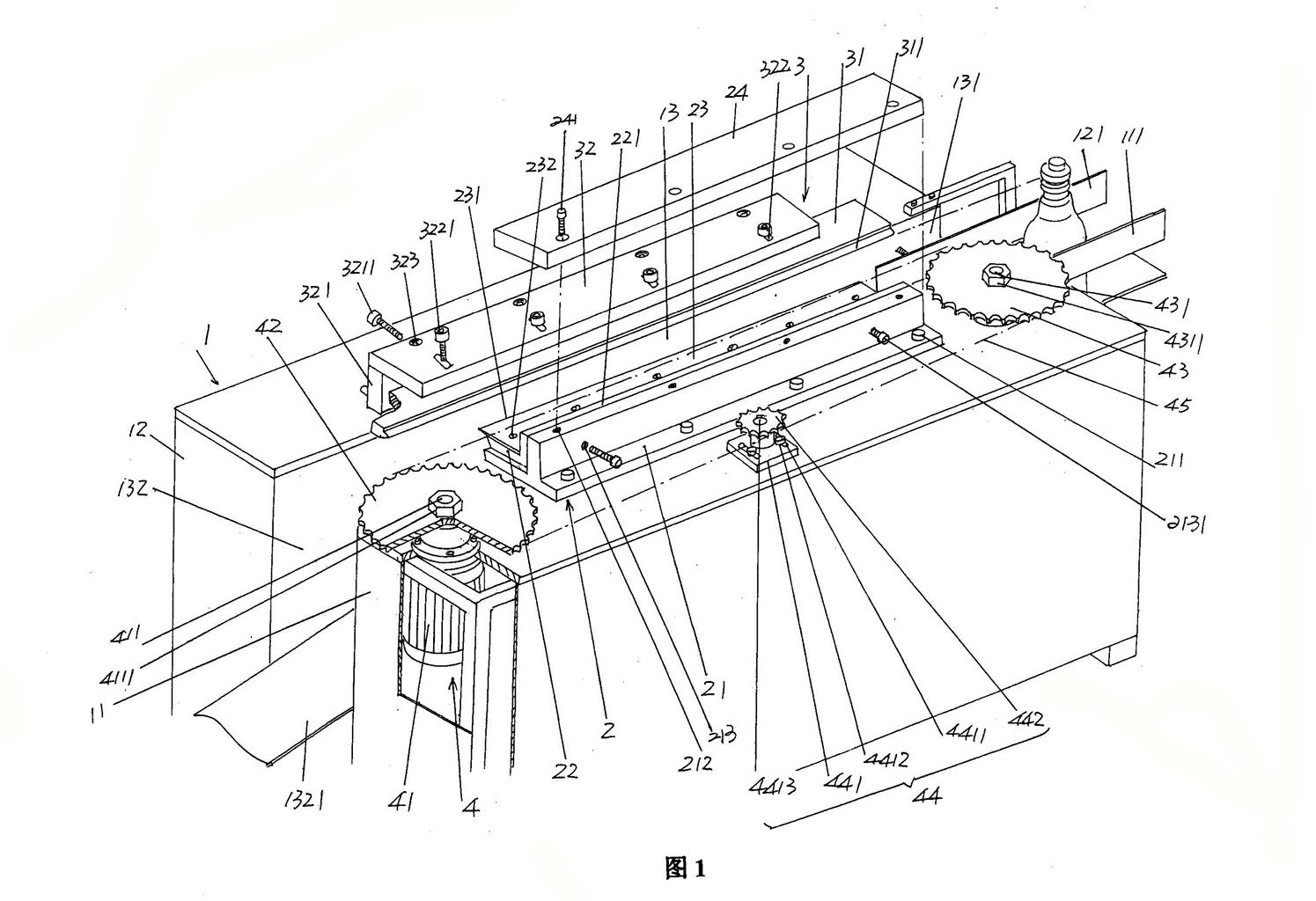
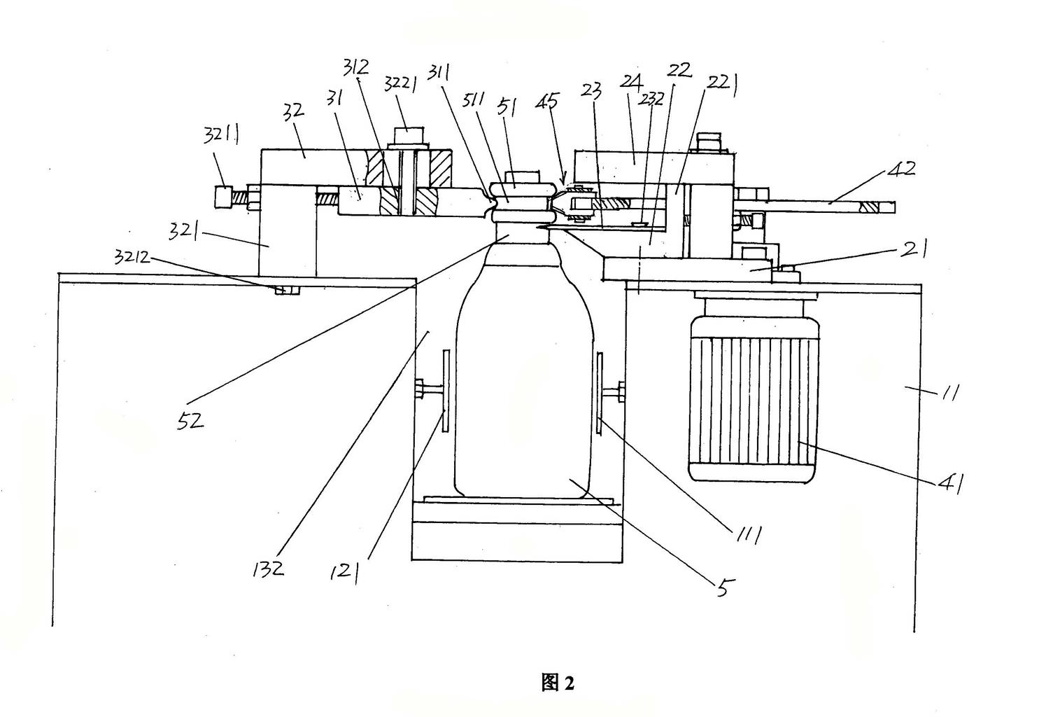
[0022] please see figure 1 , a frame 1 is given, the frame 1 has a first frame wall 11 and a second frame wall 12, the first and second frame walls 11, 12 remain parallel to each other in the length direction, and maintain a distance between each other spacing, by this spacing constitutes the bottle moving channel 13, one end of the bottle moving channel 13 is figure 1 The shown right end is the inlet...


PUM


Abstract

The utility model relates to a plastic bottle mouth rotary cutter, which belongs to the technical field of supporting facilities for automatic blow molding blow molding machines. It includes a frame, which is composed of first and second frame walls, and a bottle moving channel is formed between the first and second frame walls; the bottle mouth flash cutting mechanism is arranged on the first frame wall the top of the bottle; the bottle guiding mechanism is arranged on the top of the second frame wall and corresponds to the bottle mouth flash cutting mechanism; the bottle automatic traction mechanism is arranged on the first frame wall. Advantages: It can guarantee the normal operation of the automatic blow molding machine and avoid complicating the structure of the automatic blow molding machine, which is beneficial to improve the efficiency of cutting the flash of the bottle mouth and the regularity of the incision, and overcome the labor intensity of manual work Large and lack of manpower input, the overall structure is simple and easy to operate.

Description

technical field [0001] The invention belongs to the technical field of supporting facilities for automatic blow molding and blow molding machines, and in particular relates to a plastic bottle mouth rotary cutter. Background technique [0002] As is well known in the industry, automatic blow molding machines can efficiently blow bottles such as baby bottles, beverage bottles, cosmetic bottles, pharmaceutical liquid bottles and various condiments, but due to technological reasons There is a flash at the mouth of the bottle, which is also commonly referred to as process waste, and it needs to be cut off before it can be put on the market as a qualified product. [0003] At present, there are two ways to remove the flash of the bottle mouth. One is to use manual removal. The disadvantage of manual removal is that it requires a lot of manpower, low efficiency, high labor intensity and irregular incision; The cut-off mechanism on the plastic-blow molding machine is typically rem...

Claims


Application Information

Patent Timeline
IPC IPC(8): B29C49/72
Inventor 许卫明席丹
Owner SUZHOU TONGDA MOLD
Learn More