A Lens Design Method for Square Uniform Light Spot

A lens design and square technology, which is applied in the field of lens design where the illuminated surface is a square uniform light spot, can solve the problems of uneven illumination of the illuminated surface and difficulty in meeting customer requirements.

Active Publication Date: 2011-12-21
SHANGHAI SANSI ELECTRONICS ENG +3
View PDF3 Cites 12 Cited by
  • Summary
  • Abstract
  • Description
  • Claims
  • Application Information

AI Technical Summary

Problems solved by technology

If the illuminated surface is circular, elliptical, etc., without increasing the number of lamps, there will inevitably be dark areas and blind spots at the junction of adjacent lamps, which will make the illumination of the illuminated surface uneven.
It is difficult to meet the requirements of customers

Method used


Image

  • A Lens Design Method for Square Uniform Light Spot
  • A Lens Design Method for Square Uniform Light Spot
  • A Lens Design Method for Square Uniform Light Spot

Examples


Embodiment Construction

[0026] The specific design steps of this design method will be described in detail below through graphic and text descriptions.

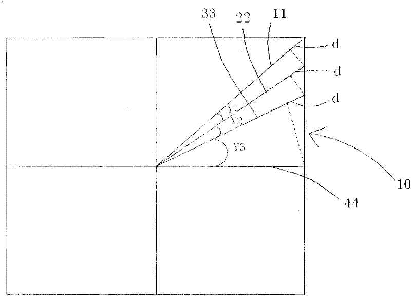
[0027] Such as figure 1 As shown, the square spot is first divided into eight centrally symmetrical areas with an angle of 45 degrees along the axis of symmetry, and one of the areas 10 is used as the design object of the present invention, and the following design steps are all completed in this area 10. The region 10 is divided into n (n≥2) corner regions. For the sake of clarity in the illustration, this embodiment is divided into three corner regions, the included angles are γ1, γ2, and γ3, and the corners are 11 and γ3 respectively. 22, 22 and 33, 33 and 44, the length difference between the two sides of each included angle is d.

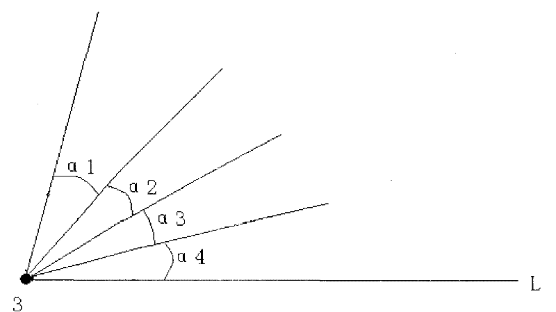
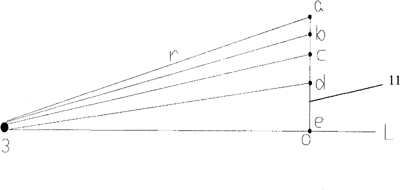
[0028] Such as figure 2 As shown, starting from the corner area with an included angle γ1, the plane passing through one of its corner sides 11 and the optical axis L of the light source 3 is the first incident pl...


PUM


Abstract

The invention discloses a method for designing a lens with a uniform square light spot. The method comprises the following steps of: firstly dividing the square light spot into eight centrosymmetric areas along an axis of symmetry, and partitioning one of the eight centrosymmetric areas into n (n is larger than or equal to 2) angular areas, wherein the difference of the lengths of two angle edgesof each angular area is constant; respectively taking one plane formed by one angular edge passing through each angular area and an optical axis as an incidence surface, partitioning a luminous area of a light source on the incidence surface arranged on one side of the optical axis into a plurality of small angles according to luminous intensity along a distribution rule of luminous angles so as to make the luminous fluxes of lights distributed in each small angle equal, partitioning the angular edge of each incidence surface into a plurality of small sections one-to-one corresponding to the small angles, sequentially obtaining the shapes of the sections of a lens on a first surface and a second surface of each incidence surface according to a refraction law, and respectively rotating thesections of the lens around the optical shaft in an angular area, wherein the optical shaft is arranged in the angular area, and a rotation angle is equal to the angle of the angular area; and obtaining the octant shape of the lens; and obtaining the whole shape of the lens according to a centrosymmetry raw. The method disclosed by the invention is simple, visualized and flexible.

Description

technical field [0001] The invention relates to a design method of an optical element, more specifically, to a design method of a lens whose illuminated surface is a square uniform light spot. Background technique [0002] When LEDs are used in engineering lighting, different lenses are often designed for light distribution according to different usage occasions or customer requirements. In some places of use, such as underground garages, squares, etc., it is usually not desirable to use too many lamps, but it is hoped that the illumination can be uniform. If the illuminated surface is circular, elliptical and other light spot shapes, without increasing the number of lamps, there will inevitably be dark areas and blind spots at the junction of adjacent lamps, which will make the illumination of the illuminated surface uneven. Therefore, it is difficult to meet the requirements of customers. In order to achieve uniform illumination of the illuminated area with fewer lamps, ...

Claims


Application Information

Patent Timeline
Patent Type & Authority Applications(China)
IPC IPC(8): F21V5/04F21Y101/02
Inventor 周士康陈春根李晟
Owner SHANGHAI SANSI ELECTRONICS ENG
Why Eureka
Try Eureka