Solar Concentrator Tracking Device

A technology of solar concentrating and tracking devices, which is applied in the field of solar energy utilization, can solve problems that affect technical indicators and its application range, and are not very satisfactory, and achieve the effect of easy understanding of the principle, low manufacturing cost, and good concentrating effect

Inactive Publication Date: 2011-12-21
王瑞峰
View PDF4 Cites 8 Cited by
  • Summary
  • Abstract
  • Description
  • Claims
  • Application Information

AI Technical Summary

Problems solved by technology

[0011] It can be seen from the above description that although the patent has made obvious progress, it is still not very sati

Method used


Image

  • Solar Concentrator Tracking Device
  • Solar Concentrator Tracking Device
  • Solar Concentrator Tracking Device

Examples


Embodiment 1

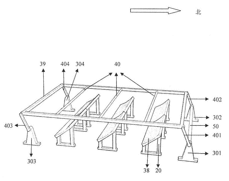
[0044] figure 1 It is a perspective view showing the embodiment of the first solar spot tracking device of the present invention.

[0045] In the figure, 20 represents the support; 301 represents the first support on the north side; 302 represents the second support on the north side; 303 represents the first support on the south side; 304 represents the second support on the south side; 38 represents the reflective condenser; 39 represents Frame; 40 represents the light energy conversion component; 50 represents the horizontal axis; 401 represents the first support rod; 402 represents the second support rod; 403 represents the third support rod; 404 represents the fourth support rod;

[0046] attached by figure 1It can be seen that the present embodiment has three rows of reflective condensers 38 and three rows of brackets 20 for fixing the reflective condensers 38 . All the brackets carry the reflective condenser 38 and are fixed in the same plane. The frame 39 is made in...

Embodiment 2

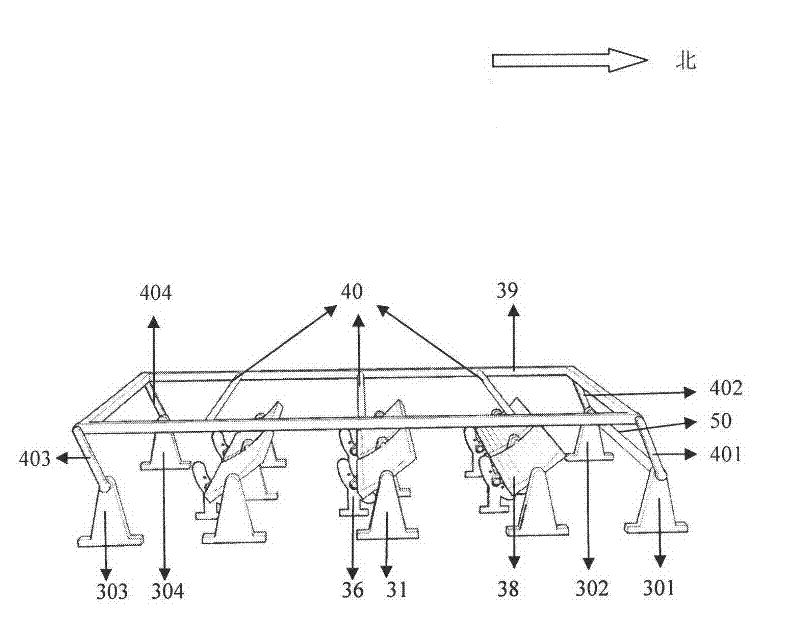
[0050] figure 2 It is a perspective view showing the embodiment of the second solar spot tracking device of the present invention.

[0051] In the figure, 31 represents a support; 38 represents a reflective condenser; 36 represents a reflective condenser positioning device; 39 represents a frame; 40 represents a light energy conversion component; 50 represents a horizontal axis; 401 represents a first support rod; 402 represents a second support rod; 403 represents the third support rod; 404 represents the fourth support rod; 301 represents the first support on the north side; 302 represents the second support on the north side; 303 represents the first support on the south side; 304 represents the second support on the south side.

[0052] attached by figure 2 It can be seen that this embodiment has three rows of reflective condenser mirrors 38 and three rows of supports 31 for supporting the reflective condenser mirrors 38 . All supports are fixed on the same plane. On ...

Embodiment 3

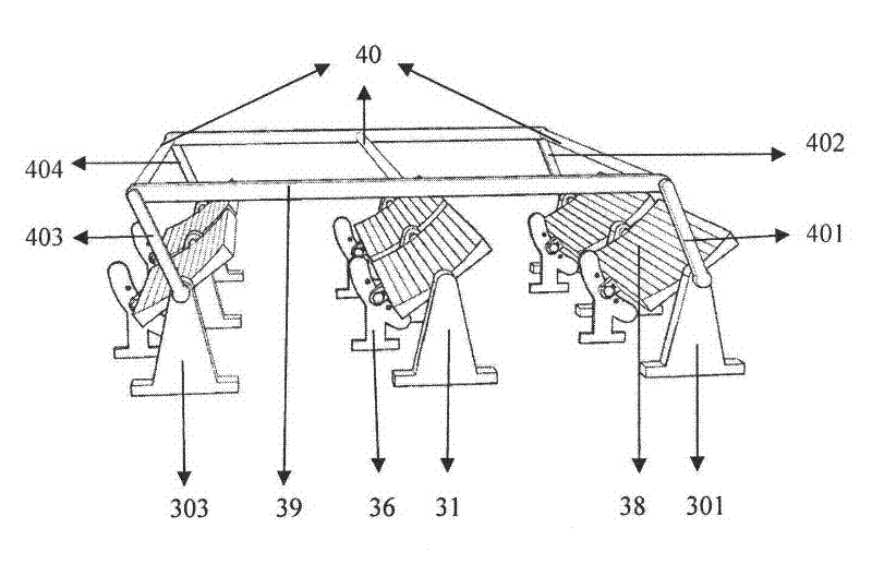
[0057] image 3 It is a perspective view showing another embodiment of the second solar spot tracking device of the present invention. It can be seen from the figure that this embodiment is actually a simplification of the previous embodiment. The difference is that the supports 301 , 302 , 303 and 304 used to support the supporting rods in the above embodiments are also used to support the reflective condenser 38 , and the rotating shaft 50 is also omitted.

[0058] In the figure, 31 represents a support; 38 represents a reflective condenser; 36 represents a reflective condenser positioning device; 39 represents a frame; 40 represents a light energy conversion component; 401 represents a first support rod; 402 represents a second support rod; 403 represents a third support Rod; 404 represents the fourth support rod; 301 represents the first support on the north side; 302 represents the second support on the north side; 303 represents the first support on the south side; 304 ...


PUM


Abstract

The invention provides a solar energy condensation tracking device, which comprises multiple rows of brackets, reflection condensing mirrors, a horizontal frame, supporting rods, supports and a control system, wherein the horizontal frame is provided with light energy conversion components; the control system drives the horizontal frame to rotate; the rows of brackets are fixedly arranged on a horizontal plane in parallel and are motionless in four seasons; the row number of the reflection condensing mirrors corresponds to the row number of the brackets; the reflection condensing mirrors are respectively fixed on the bracket and are motionless in four seasons; the horizontal fame provided with the light energy conversion components is fixed into a whole; the row number of the light energy conversion components corresponds to the row number of the reflection condensing mirrors; at least four supporting rods are provided; the upper end of each supporting rod is respectively connected with four connection points of the frame in a rotating mode by a spindle; the lower end of each supporting rod can be respectively connected with one support in a rotating mode by the spindle; and all the supports and the brackets are fixed on the same plane. The solar energy condensation tracking device has the beneficial effect that a condensation effect better than the condensation effect in the prior art can be obtained no matter that the incidence angle of sunlight is big or small.

Description

technical field [0001] The invention relates to the field of solar energy utilization, in particular to a solar concentrated light tracking device. Background technique [0002] Due to the increasing scarcity of traditional energy such as oil and coal and environmental pollution, people pay more attention to the use of clean energy such as solar energy and wind energy. Among them, the research and development of solar energy has a history of several decades. [0003] The utilization of solar energy mainly has two aspects: one is solar thermal application, and the other is solar photovoltaic application. The solar spot tracking technology can play a positive role in promoting the development of these two application fields. For photothermal applications, solar concentrated tracking technology can effectively increase the energy density of sunlight on light energy conversion components, thereby generating higher temperatures, which can further expand the application range of...

Claims


Application Information

Patent Timeline
IPC IPC(8): H01L31/042H01L31/052G05D3/00F24J2/38F24S23/70F24S50/20H02S20/32H02S40/22
CPCY02E10/52Y02E10/50Y02E10/47
Inventor 王瑞峰
Owner 王瑞峰
Why Eureka
Try Eureka