Optical collector with multi-section circular arc

A concentrator and arc technology, applied in the field of solar concentrating, can solve the problems of difficulty in manufacturing, concentrating bandwidth and high cost, and achieve the advantages of reducing the difficulty and cost of processing, reducing the difficulty of installation and adjustment, and increasing the uniformity of concentrating light. Effect

Inactive Publication Date: 2010-02-24
SOUTHEAST UNIV
View PDF0 Cites 16 Cited by
  • Summary
  • Abstract
  • Description
  • Claims
  • Application Information

AI Technical Summary

Problems solved by technology

[0003] For solar concentrating photovoltaic systems, the commonly used Fresnel lens is a point-focusing refracting concentrator, which can achieve high-magnification concentrating light, but it still has many problems: it is difficult to increase the area of ​​the daylight opening; The optical efficiency is difficult to improve due to limitations; the stability and reliability of polymer materials are poor; the cost is high

Method used


Image

  • Optical collector with multi-section circular arc
  • Optical collector with multi-section circular arc
  • Optical collector with multi-section circular arc

Examples


Embodiment 1

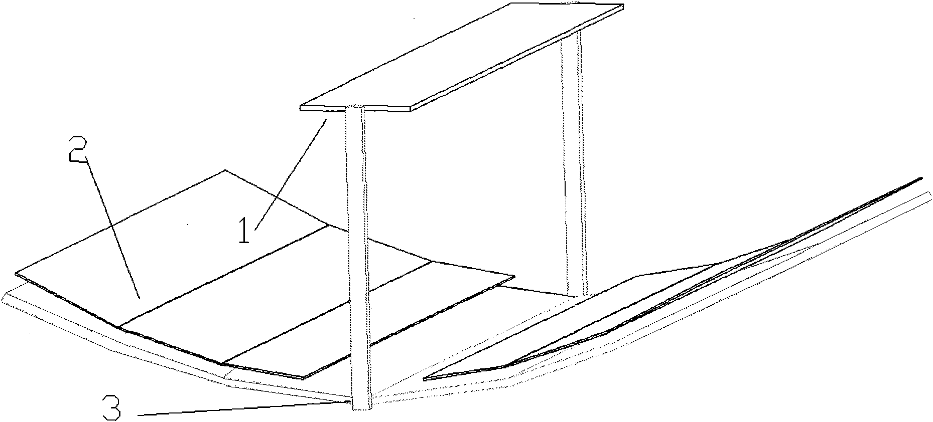
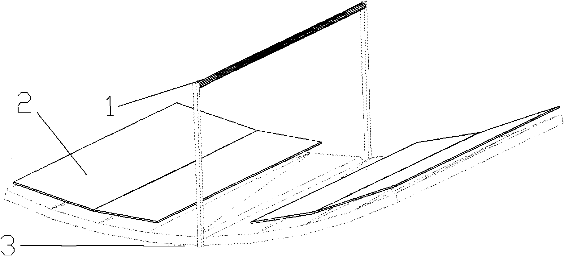
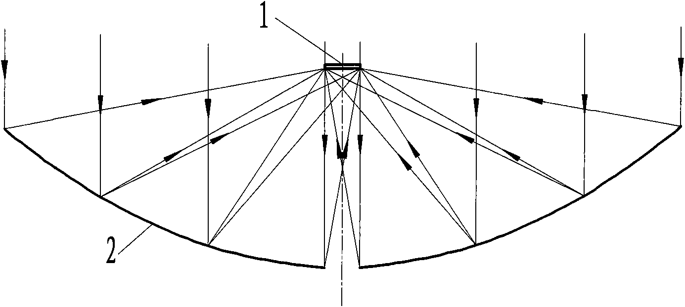
[0026] The receiver 1 uses a photovoltaic cell assembly. The solar concentrator makes sunlight incident on the receiving surface along the central axis through the tracking system, and the light reaches the multi-section arc reflector 2. After mirror reflection, each section of arc mirror The reflected light can reach and cover the entire solar photovoltaic cell assembly, and the reflector and the photovoltaic cell assembly are fixed by the supporting frame 3 . image 3 It is a schematic diagram of the light path, using three arcs as reflectors, the arc length is 1 meter, the radius is 5 meters, 5.8 meters, 7.2 meters, and the height of the battery module is 1.7 meters.

Embodiment 2

[0028] The receiver 1 uses a heat collecting tube. The solar concentrator makes sunlight incident on the receiving surface along the central axis through the tracking system, and the light reaches the multi-section arc reflector 2. After being reflected by the mirror, the reflection of each arc mirror The light can reach the heat collecting tube more concentratedly, and the reflector and the heat collecting tube are fixed by the support frame 3 . Figure 4 It is a schematic diagram of the optical path, using two arcs as reflectors, the arc length is 1 meter, the radius is 4 meters, 4.86 meters, and the height of the battery module is 1.927 meters.

Embodiment 3

[0030] The receiver 1 uses a photovoltaic cell assembly. The solar concentrator makes sunlight incident on the receiving surface along the central axis through the tracking system, and the light reaches the multi-section arc reflector 2. After mirror reflection, each section of arc mirror The reflected light can reach and cover the entire solar photovoltaic cell assembly, and the reflector and the photovoltaic cell assembly are fixed by the supporting frame 3 . Figure 5 It is a schematic diagram of the optical path, using three arcs as reflectors, the arc length is 1 meter, the radius is 5 meters, and the height of the battery module is 1.7 meters. Such a design can reduce the influence of wind pressure on the mirror surface, and significantly reduce the cost of manufacturing the mirror surface. The disadvantage is that the light concentration ratio is relatively small compared with the design of Example 1.


PUM


Abstract

An optical collector with multi-section circular arc relates to an optical collector utilizing solar energy, particularly a linear focusing reflecting type optical collector. The optical collector comprises a receiver (1), a reflector with multi-section circular arc (2) and a bracket (3), wherein the receiver (1) is above the reflector with multi-section circular arc (2) and is in the position ofthe focal line formed by the reflector with multi-section circular arc (2). The bracket (3), under the reflector with multi-section circular arc (2) is for fixing the reflector with multi-section circular arc (2) and extends out a supporting rod from the gap of the reflector with multi-section circular arc (2) to support the receiver (1). By adopting the reflecting type linear optical collector, the problems of the refracting type optical collector, that the cost is high, the size is difficult to amplify, the optical efficiency is limited by index of refraction, etc., can be solved. The reflector with multi-section circular arc instead of the parabolic reflector can obviously decrease the processing difficulty and manufacturing cost and also can decrease the mounting difficulty and promotethe concentrating ratio.

Description

technical field [0001] The invention relates to a solar energy utilization concentrating device, in particular to a linear focus reflection type concentrating device, which belongs to the technical field of solar concentrating. Background technique [0002] As a clean, non-polluting renewable energy source, solar energy is considered an important part of the world's energy strategy for its development and utilization. The utilization of solar energy mainly includes two categories: solar thermal utilization and solar photovoltaic power generation. In the utilization of solar heat, in order to obtain high-temperature steam, electric energy, etc., concentrating technology must be used. In solar photovoltaic technology, light concentrating technology is used to reduce the area of ​​photovoltaic cells used in a system, thereby reducing costs and achieving high photoelectric conversion efficiency. Therefore, a large number of scientific researchers have explored and studied the ...

Claims


Application Information

Patent Timeline
IPC IPC(8): F24J2/10H01L31/052F24S23/70
CPCY02E10/40Y02E10/52
Inventor 张耀明余雷王军
Owner SOUTHEAST UNIV
Why Eureka
Try Eureka