Novel combined double-plunger assembly

A combined, double-plunger technology, which is applied in variable capacity pump components, components of pumping devices for elastic fluids, machines/engines, etc., can solve the problem of harsh working conditions, increased labor intensity of operators, and occupancy Liquidity and other issues, to achieve the effect of processing difficulty and low cost, improve convenience, and facilitate processing

Active Publication Date: 2020-12-11
HUBEI PETROKH MACHINE MFG
View PDF6 Cites 0 Cited by
  • Summary
  • Abstract
  • Description
  • Claims
  • Application Information

AI Technical Summary

Problems solved by technology

[0002] With the deepening of the country's development of the oil field, a large number of plunger pumps with complicated models have been put into the market, and they are playing an increasingly important role in the oil field. As the core component of the reciprocating linear motion of the plunger pump, the plunger is passed Convert the mechanical energy of the power end into the pressure energy of the liquid. At present, the domestic and foreign markets generally adopt a one-to-one corresponding structure of a diameter plunger corresponding to a pump head body. Once the output pressure and displacement of the on-site construction conditions change, it must be disassembled. Replacing the diameter plunger and pump head body of the hydraulic end of the corresponding plunger pump, on the one hand, the field operating conditions in the oil field are harsh, and dismantling the pump to replace accessories takes a lot of construction time, increasing the labor intensity of the operator, which is time-consuming and laborious; on the other hand, the pump head The body, plunger and seal assembly are equipped with a wide variety of accessories, which occupy a large amount of working capital

Method used


Image

  • Novel combined double-plunger assembly
  • Novel combined double-plunger assembly
  • Novel combined double-plunger assembly

Examples


Embodiment Construction

[0037] The technical solutions of the present invention will be clearly and completely described below in conjunction with specific embodiments. Apparently, the described embodiments are only some of the embodiments of the present invention, not all of them. Based on the embodiments of the present invention, all other embodiments obtained by persons of ordinary skill in the art without creative efforts fall within the protection scope of the present invention.

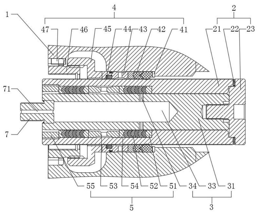
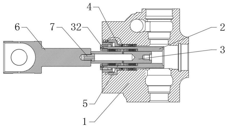
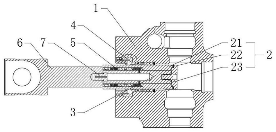
[0038] refer to Figure 1 ~ Figure 3 , a new combined double plunger assembly, including the outer plunger assembly 2 installed in the plunger chamber of the pump chamber plunger seal assembly 1, the inner plunger assembly 3 and the inner plunger assembly 3 Connected driving device 6, the driving device 6 is a pull rod at the power end that converts the rotary motion of the prime mover into the linear reciprocating motion of the outer plunger assembly 2 or the inner plunger assembly 3 in the plunger pump, and the inne...


PUM


Abstract

The invention relates to the technical field of plunger pumps, and discloses a novel combined double-plunger assembly which comprises an outer plunger assembly and an inner plunger assembly which areinstalled in a pump cavity plunger sealing assembly, and the inner plunger assembly is installed in an inner cavity of the outer plunger assembly; and an outer plunger sealing assembly is arranged between the outer plunger assembly and the pump cavity plunger sealing assembly, an inner plunger sealing assembly is arranged between the inner cavity of the outer plunger assembly and the inner plungerassembly. According to the novel combined double-plunger assembly, by the adoption of a combined double-plunger assembly structure with an inner plunger and an outer plunger, the outer plunger assembly and the inner plunger assembly work relatively independently, so that when the outer plunger assembly works, the output displacement and pressure of a whole pump correspond to diameter parameters of an outer plunger body, the inner and outer plunger assemblies with the different diameters can be rapidly switched to be used without disassembling the pump to replace the plungers or a pump head body, and the requirements for different output displacement and pressure working conditions on site are met; and the effects are achieved through one step, the design is ingenious, time and labor are saved, and convenience and quickness are achieved.

Description

technical field [0001] The invention relates to the technical field of plunger pumps, in particular to a novel combined double plunger assembly. Background technique [0002] With the deepening of the country's development of the oil field, a large number of plunger pumps with complicated models have been put into the market, and they are playing an increasingly important role in the oil field. As the core component of the reciprocating linear motion of the plunger pump, the plunger is passed Convert the mechanical energy of the power end into the pressure energy of the liquid. At present, the domestic and foreign markets generally adopt a one-to-one corresponding structure of a diameter plunger corresponding to a pump head body. Once the output pressure and displacement of the on-site construction conditions change, it must be disassembled. Replacing the diameter plunger and pump head body of the hydraulic end of the corresponding plunger pump, on the one hand, the field op...

Claims


Application Information

Patent Timeline
IPC IPC(8): F04B53/14F04B53/18
CPCF04B53/14F04B53/143F04B53/18
Inventor 郑磊梁峰
Owner HUBEI PETROKH MACHINE MFG
Why Eureka
Try Eureka