

Noise reduction earphone interface structure
A technology of noise-cancelling earphones and earphones, applied in the direction of earpieces/earphone accessories, etc.
- Summary
- Abstract
- Description
- Claims
- Application Information
AI Technical Summary
Problems solved by technology
Method used
Image

Examples
Embodiment 1
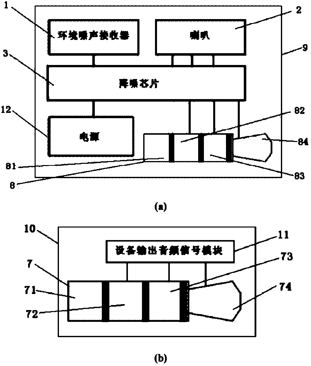
[0047] Such as figure 1 As shown, the noise reduction earphone interface architecture of the present invention includes: environmental noise receiver 1, speaker 2, noise reduction chip 3, earphone end microphone 4, earphone end control switch 5, device end control switch 6, and device end audio interface 7 , earphone end audio interface 8, equipment output audio signal module 11, power supply 12 and earphone microphone output interface 13, wherein: the power input end of noise reduction chip 3, the environment noise receiving end, output end and audio frequency input end are controlled with earphone end respectively The switch 5, the environmental noise receiver 1, the speaker 2 are electrically connected to the earphone end audio interface 8, the control end of the earphone end control switch 5 and the earphone microphone input end are respectively electrically connected to the earphone end audio interface 8 and the earphone end microphone 4, and the device end The audio inte...
Embodiment 2
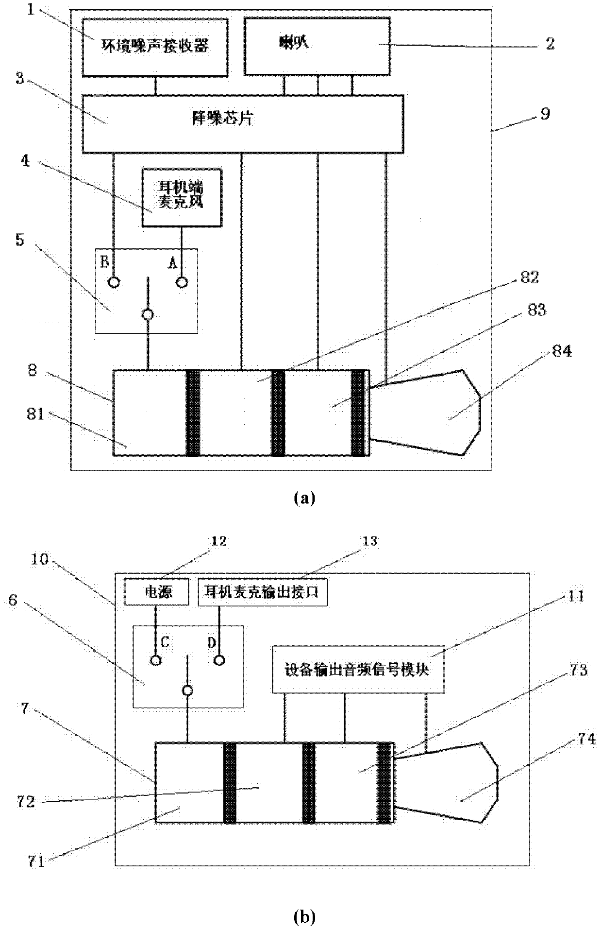
[0065] The noise reduction earphone interface architecture of the present invention includes: an environmental noise receiver 1, a speaker 2, a noise reduction chip 3, an earphone end microphone 4, an earphone end control switch 5, an equipment end control switch 6, an equipment output audio signal module 11, an earphone Microphone output interface 13, equipment end audio interface 7, earphone end audio interface 8 and power supply 12, wherein: earphone end control switch 5 is electrically connected with environmental noise receiver 1, earphone end microphone 4 and earphone end audio interface 8 respectively, earphone end The audio interface 8 is electrically connected to the audio input end of the loudspeaker 2, and the audio input end, the ambient noise receiving end, the output end and the power input end of the noise reduction chip 3 are respectively connected to the equipment output audio signal module 11, the equipment end control switch 6, and the equipment end. Audio in...
Embodiment 3
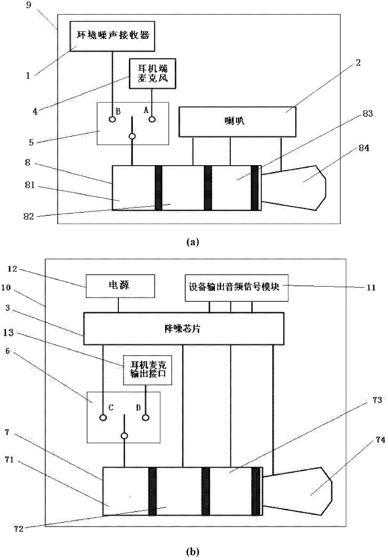
[0083] The noise reduction earphone interface architecture of the present invention includes: noise reduction chip 3, speaker 2, earphone end microphone 4, device end control switch 6, device end audio interface 7, earphone end audio interface 8, device output audio signal module 11, power supply 12 and earphone microphone output interface 13, wherein: earphone end audio interface 8 is electrically connected with earphone end microphone 4 and loudspeaker 2 respectively, and the audio frequency input end, ambient noise receiving end, output end and power input end of noise reduction chip 3 are respectively connected with equipment output The audio signal module 11, the device-side control switch 6, the device-side audio interface 7 are electrically connected to the power supply 12, and the device-side control switch 6 is electrically connected to the device-side audio interface 7, the noise reduction chip 3 and the earphone microphone output interface 13 respectively. During the...
PUM
 Abstract
Description
Claims
Application Information