Plasma Power Generation System

A plasma and electrode technology, applied in the field of in vitro physics, can solve problems such as low efficiency and structural damage

Inactive Publication Date: 2011-12-21
RGT UNIV OF CALIFORNIA
View PDF10 Cites 22 Cited by
  • Summary
  • Abstract
  • Description
  • Claims
  • Application Information

AI Technical Summary

Problems solved by technology

Disadvantages of the neutron reaction are: (1) the fast neutron stream creates many problems, including structural damage to the reactor walls and, for most materials of manufacture, high levels of radioactivity; Electrics harvest their energy, which is very inefficient (less than 30%)
Although there hav

Method used


Image

  • Plasma Power Generation System
  • Plasma Power Generation System
  • Plasma Power Generation System

Examples


Embodiment Construction

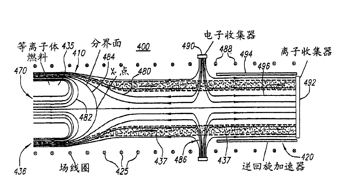
[0073] As illustrated above, the plasma power generation (PEG) system of the present invention preferably includes a collision beam fusion reactor (CBFR) coupled to a direct energy conversion system. As mentioned above, an ideal fusion reactor solves the problem of anomalous migration of both ions and electrons. The solution to the anomalous migration problem found here utilizes a closed system with a magnetic field in a field-reversing configuration (FRC). In such a way, that most ions have large non-adiabatic orbitals, making them insensitive to short-wavelength fluctuations that cause anomalous migration of adiabatic ions, which is avoided by magnetic field confinement in the FRC. In particular, there are regions in the FRC where the magnetic field disappears, making it possible to have plasmas that include mostly non-adiabatic ions. For electrons, the anomalous transfer of energy is avoided by tuning the applied magnetic field so that a strong electric field appears. The...


PUM


Abstract

The present invention relates to a plasma power generation system. A system and device for controlling fusion and direct-to-electricity conversion of fusion product energy in a field reverse configuration (FRC) magnetic topology. Preferably, the plasma ions are magnetically confined in the FRC, while the plasma electrons are electrostatically confined in a deep energy well created by tuning the applied magnetic field. In this configuration, the ions and electrons can be of such density and temperature that upon collision they are fused together by nuclear forces to form fusion products in the form of a ring beam. As the fusion product ions spiral through the electrodes of the inverse cyclotron converter, energy is removed from them. Advantageously, fusion fuel plasmas usable with the present confinement and energy conversion system include advanced (non-neutron) fuels.

Description

[0001] This application is a divisional application of the application with the application number 200680007428.2, the application date is March 7, 2006, and the invention name is "plasma power generation system". technical field [0002] This invention relates generally to the field of plasma physics, and more particularly to methods and apparatus for confining plasmas to enable nuclear fusion energy and for converting energy from fusion products into electrical energy. Background technique [0003] Fusion is the process by which two light nuclei combine to form a heavier nucleus. The fusion process releases enormous amounts of energy in the form of fast-moving particles. Because the nuclei are positively charged - due to the protons contained within - there is a repulsive electrostatic or Coulomb force between them. For two fused nuclei, this repulsive force barrier must be overcome. This occurs when the two nuclei are sufficiently close together that the short distance ...

Claims


Application Information

Patent Timeline
IPC IPC(8): H05H1/46H05H1/12G21B1/05
CPCG21B1/05Y02E30/122Y02E30/126G21B1/052Y02E30/10H01J7/24G21B1/00
Inventor N.罗斯托克M.宾德鲍尔F.韦塞尔A.钟V.拜斯特里特斯基Y.宋M.安德森E.加拉特艾伦·文德里
Owner RGT UNIV OF CALIFORNIA
Why Eureka
Try Eureka