camera equipment

一种摄像设备、摄像像素的技术,应用在图像通信、辐射控制装置、电视等方向,能够解决像素开口率下降、像素感光度降低、没有提高S/N比等问题

Inactive Publication Date: 2011-12-21
CANON KK
View PDF9 Cites 15 Cited by
  • Summary
  • Abstract
  • Description
  • Claims
  • Application Information

AI Technical Summary

Problems solved by technology

For this reason, in the case of using an electronic viewfinder and in the case of a moving picture mode, etc., the focus detection pixels are not read out, so although the frame rate of a moving picture can be increased, there is a problem that when a moving picture is being displayed , unable to perform high-speed focus detection using phase difference technology
However, there is a problem that the number of signal lines arranged between pixels increases, resulting in a decrease in the aperture ratio of the pixel and a decrease in the sensitivity of the pixel.
However, there is a problem in that although the outputs are added after readout, since the noise from the pixel amplifier or the readout gain amplifier etc. is also added many times, it does not Improve S / N ratio

Method used


Image

  • camera equipment
  • camera equipment
  • camera equipment

Examples


no. 1 example

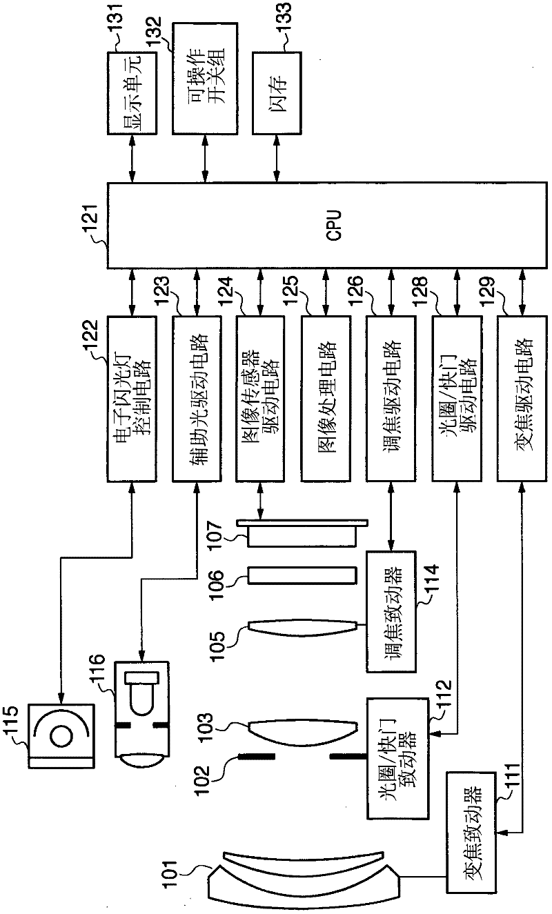
[0027] figure 1 is a diagram showing the structure of a camera (image pickup apparatus) according to a first embodiment of the present invention, and shows a digital camera in which a camera body having an image sensor and an image pickup lens is integrated in a single unit. exist figure 1 In , reference numeral 101 denotes a first lens group disposed at an end portion of an imaging optical system (image forming optical system), wherein the first lens group is held to be movable back and forth in the optical axis direction. Reference numeral 102 denotes an aperture / shutter, and controlling the opening diameter of the aperture / shutter 102 enables adjustment of the amount of light during imaging; during still image capturing, the aperture / shutter 102 also functions as an exposure time adjustment shutter. Reference numeral 103 denotes a second lens group. The aperture / shutter 102 and the second lens group 103 move back and forth in the direction of the optical axis as a whole, ...


PUM


Abstract

An image capturing apparatus includes: an image sensor including image sensing pixels that generate a signal for image generation, and focus detection pixels dividing the pupil region of an imaging lens into pupil regions and generating a signal for phase difference detection by photoelectrically converting object images from the pupil regions obtained by the division; a switching unit that switches between an all-pixel readout mode in which signals from all of the multiple pixels are read out and a thinning readout mode in which the signals of the multiple pixels are thinned and read out; and a control unit that, in the case where the mode has been switched by the switching unit to the thinning readout mode, controls the accumulation of charges in imaging rows used for image generation and focus detection rows including the focus detection pixels independent from each other.

Description

technical field [0001] The present invention relates to an imaging apparatus including an image sensor having a plurality of pixels arranged in a two-dimensional form. Background technique [0002] As general techniques for an automatic focus detection / adjustment method of an imaging apparatus using a light beam passing through an imaging lens, contrast detection technology (also called "blur technology") and phase difference detection technology (also called "bias technology") are known. transfer technology"). The contrast detection technique is a technique widely used in a camcorder (camcorder) and a digital still camera etc. which take a moving image, and in this case, the image sensor thereof is used as a focus detection sensor. This technique pays attention to the signal output from the image sensor, especially the high-frequency component information (contrast information) of the signal, and uses the position of the imaging lens with the highest evaluation value of th...

Claims


Application Information

Patent Timeline
Patent Type & Authority Applications(China)
IPC IPC(8): H04N5/232H04N5/353H04N5/374H01L27/146H01L27/14H04N5/335H04N5/341H04N5/345H04N5/357H04N5/3745
CPCH04N5/374H04N5/23212H01L27/14643H01L27/14627H04N5/3696H04N5/3532H01L27/14621H04N23/672H04N23/63H04N25/531H04N25/704H04N25/76H04N25/134
Inventor 谷口英则
Owner CANON KK
Why Eureka
Try Eureka