
u-shaped pinnate line

A tooth line and U-shaped technology, applied in the field of medical surgical lines, can solve the problems of poor lifting force, short holding time, uneven pulling force, etc., and achieve the effect of less surgical lines, long holding time, and large lifting force.

Inactive Publication Date: 2011-12-28
周军臣
View PDF4 Cites 3 Cited by
  • Summary
  • Abstract
  • Description
  • Claims
  • Application Information

AI Technical Summary

Problems solved by technology

[0003] The purpose of the present invention is to provide a U-shaped feather-tooth thread to solve the problem of using a single thread in the prior art. Uneven pulling force, asymmetrical left and right sides and short holding time

Method used


Image

  • u-shaped pinnate line
  • u-shaped pinnate line

Examples


Embodiment Construction

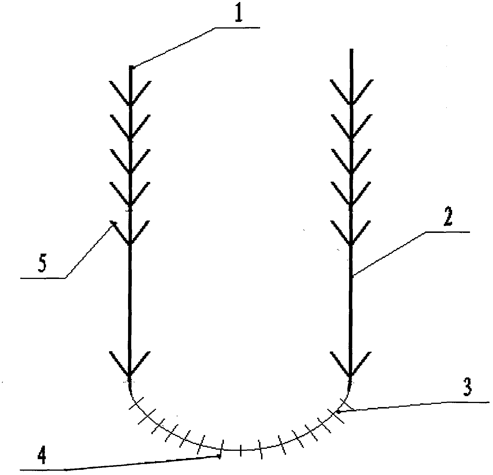
[0010] In Figure 1-2: the left line 1 and the right line 2 are both flat lines, with upwardly inclined feather teeth 5 evenly distributed on both sides, and the connecting line 3 is circular, with a length of 8-40mm. Vertical teeth 4 are evenly distributed, the length of the vertical teeth is 1-3mm, and the spacing is 3-10mm.

[0011] Instructions for use: Use a special U-shaped device, first put a U-shaped tube on the face, pass the line through the guide wire, fix one end, and pull out the U-shaped tube. The fixing method is the same as the prior art.


PUM

PropertyMeasurementUnit
Lengthaaaaaaaaaa
Lengthaaaaaaaaaa

Abstract

The invention belongs to a U-shaped feather-tooth wire, which is characterized in that: the wire is U-shaped in use, and can be divided into three parts: left wire, right wire and connecting wire. The left wire and right wire are flat wires. There are evenly distributed upward-sloping feather-like teeth, and the connecting lines are circular for light. The thread lifts the face in U-shaped units. The left thread and the right thread do not move back and forth, and can be coordinated with each other. There are few threads used in the operation. It will relax, and the plastic surgery lasts for a long time, which is suitable for promotion and use in the beauty industry.

Description

technical field [0001] The invention relates to a medical operation thread, which is a U-shaped feather tooth thread used in the beauty industry. Background technique [0002] At present, there are two kinds of surgical threads used in the beauty industry, one is general medical surgical thread, and the other is sawtooth thread made of nylon or silicone material, its structure is composed of thread body and saw-shaped teeth, mainly used for facial Lifting and plastic surgery are all arranged in a single line, one end is fixed on the head, and the other end of the face is free. This kind of surgical thread has the following disadvantages and deficiencies; (1) Since one end is free, the force is single, so the lifting strength Poor, use more threads; (2) The threads are independent, there is no coordination between each other, prone to uneven tension and asymmetrical left and right sides; (3) The holding time is short, because the surgical thread ends Free, no fixed point, wi...

Claims


Application Information

Patent Timeline
IPC IPC(8): A61B17/04
Inventor 周军臣
Owner 周军臣
Learn More