
Speed reducer transmission efficiency optimization method

A technology of transmission efficiency and optimization method, applied in design optimization/simulation, instrumentation, energy industry, etc., can solve problems such as system research, few reducer transmission efficiency modeling, single parameter, etc., to achieve strong adaptability and realize deceleration Drive efficiency and high economy

Pending Publication Date: 2022-08-02
SHANDONG UNIV OF SCI & TECH
View PDF2 Cites 1 Cited by
  • Summary
  • Abstract
  • Description
  • Claims
  • Application Information

AI Technical Summary

Problems solved by technology

However, the target selection parameters of this scheme are relatively simple. Although the transmission efficiency can be improved to a certain extent, there is still a lot of room for improvement.
[0007] With the maturity and development of the simulation analysis technology of the reducer transmission system, it provides conditions for the accurate simulation detection of the transmission efficiency of the reducer and the analysis of the main influencing factors. Optimal technology for systematic research

Method used


Image

  • Speed reducer transmission efficiency optimization method
  • Speed reducer transmission efficiency optimization method
  • Speed reducer transmission efficiency optimization method

Examples


Embodiment 1

[0152] For the secondary spur gear reducer used in the car, the above technical scheme is used to optimize the transmission efficiency of the reducer.

[0153] Specifically, in step 3, after carrying out the solid modeling of the reducer, the input of working condition parameters, and the analysis of the relationship between the optimal parameters of the transmission efficiency of the reducer and the influence of the transmission efficiency, five parameters with the largest variation amplitude are selected in the evaluation of the analysis results ( The five parameters whose change amplitude decreases sequentially from the largest) are used as the preferred parameters of the orthogonal test, and are used as the preferred parameters of the orthogonal test to optimize the transmission efficiency of the reducer in the subsequent step 4.

[0154] In step 4, when designing the orthogonal experimental scheme, since this embodiment is a two-stage spur gear reducer, the tooth width B i...

Embodiment 2

[0156] For the secondary planetary gear reducer on the scraper conveyor, the above technical scheme is used to optimize the transmission efficiency of the reducer.

[0157] Specifically, in step 3, after carrying out the solid modeling of the reducer, the input of working condition parameters, and the analysis of the relationship between the optimal parameters of the transmission efficiency of the reducer and the influence of the transmission efficiency, five parameters with the largest variation amplitude are selected in the evaluation of the analysis results ( The five parameters whose change amplitude decreases sequentially from the largest) are used as the preferred parameters of the orthogonal test, and are used as the preferred parameters of the orthogonal test to optimize the transmission efficiency of the reducer in the subsequent step 4.

[0158] In step 4, when designing the orthogonal experimental scheme, since this embodiment is a two-stage planetary gear reducer, t...


PUM


Abstract

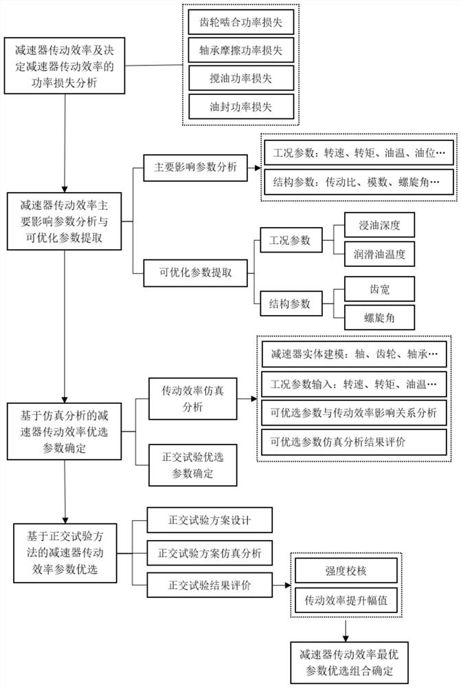
The invention relates to a method for optimizing the transmission efficiency of a speed reducer. The method comprises the following steps of: 1, proposing the transmission efficiency of the speed reducer and each power loss expression; 2, extracting structure parameters and working condition parameters which can be used for optimizing the transmission efficiency of the speed reducer; 3, establishing a speed reducer transmission efficiency simulation analysis model, analyzing the relation between the structure parameters and the working condition parameters extracted in the step 2 and the transmission efficiency, and selecting at least five parameters with the maximum influence as optimal parameters of an orthogonal test; and step 4, optimizing the transmission efficiency of the speed reducer through design of an orthogonal test scheme, simulation analysis and optimization result evaluation, and finally obtaining an optimal parameter combination meeting evaluation requirements. According to the method, influence factors are comprehensively considered in the whole optimization process, the actual operation condition is better met, the application range is wide, the method is not limited to speed reducers of specific structures, and in other words, the transmission efficiency can be greatly improved through the optimization method for speed reducers of different structures.

Description

technical field [0001] The invention relates to a method for optimizing the transmission efficiency of a reducer, and belongs to the technical field of reducers. Background technique [0002] As an important part of mechanical equipment, reducer is widely used in construction, vehicles, ships, aerospace and mining and other fields. In recent years, the rapid development of my country's industry has promoted rapid economic growth, but with it comes Severe environmental pollution and energy shortage problems, in order to solve this fundamental problem, it is necessary to improve the energy-saving technology in industrial production. The improvement of the energy-saving level of the reducer in industrial production is mainly reflected in the improvement of its transmission efficiency. [0003] The transmission efficiency of the reducer is related to the power loss of the reducer, and the power loss reflects the energy loss of the reducer in the working process. The application ...

Claims


Application Information

Patent Timeline
IPC IPC(8): G06F30/17G06F30/20G06F119/14
CPCG06F30/17G06F30/20G06F2119/14Y02P80/10
Inventor 李学艺吴宗坤颜凤李远达葛淑磊莫凡毛蒲军
Owner SHANDONG UNIV OF SCI & TECH
Learn More