A combination grid

A technology of grid frame and steel structure beam is applied in the field of combined grid frame, which can solve the problems of complicated design and calculation, difficult to make template, difficult construction, etc., and achieve the effect of simplifying the calculation process and improving the calculation speed.

Active Publication Date: 2011-12-28
SHENZHEN GENERAL INST OF ARCHITECTURAL DESIGN & RES
View PDF4 Cites 5 Cited by
  • Summary
  • Abstract
  • Description
  • Claims
  • Application Information

AI Technical Summary

Problems solved by technology

However, the combined grid has inevitable disadvantages: the design and calculation are complicated, and the construction is difficult
[0004] In terms of construction, its complexity lies in the following three aspects: First, because the concrete slab is composed of slabs, rib beams and cross beams, the concrete slab is generally a triangular slab, such as figure 1 and image 3 As shown, formwork is difficult to make when prefabricating components
Secondly, when combining the concrete slab with the steel structure, due to construction errors (such as irregular concrete slab production, large welding deformation of the steel structure, error in the blanking size of the steel structure, etc.), the reserved joint between the slabs or If it is too large or too small, it will be difficult to weld concrete embedded parts and steel structure nodes, the welder's operating surface will be limited, and the quality of welds will be difficult to guarantee
Finally, after the joints are filled, the bonding between the rib concrete and the newly poured fine stone concrete is not ideal, making it difficult for adjacent rib beams to be connected as a whole through the bonding of the fine stone concrete between the gaps. There is a deviation between the calculation model and the actual structure. On the other hand, if the grid frame is used as a roof, it is easy to seep water and affect the use

Method used


Image

  • A combination grid
  • A combination grid
  • A combination grid

Examples


Embodiment Construction

[0023] The detailed structure of this patent will be further described below in conjunction with the accompanying drawings.

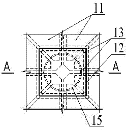
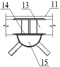
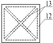
[0024] combine Figure 4 A combined grid structure shown includes an upper chord and a lower chord of the grid, the lower chord is welded below the upper chord, and the upper chord includes an integral concrete slab 1 and steel structural beams 2, the steel structural beams 2 are arranged in a cross. further combined Figure 5 , the steel structure beam 2 is a ⊥-shaped beam, the vertical part is embedded in the integral concrete slab 1, and the transverse part is arranged on the lower side of the integral concrete slab 1. The lower chord is the spherical segment node 5 of the steel structure, which is connected below the intersection position of the steel structure beams 2 through the top plate 4, and the web bar 6 is connected below. The structure of the node 5 is very simple, only need to weld the ⊥-shaped beam on the roof 2.

[0025] In the intern...


PUM


Abstract

The invention relates to the field of building structures. The technical problem to be solved of the invention is to overcome the defects in the prior art and provide a novel combined net support structure, which is used for fulfilling the aims of simple design computation, convenience for construction, high waterproofness, capability of bearing high loads and the like. The combined net support structure comprises a net support upper chord, a lower chord and a web member, wherein the upper end of the web member is connected with the lower side of the upper chord; and the lower end of the web member is connected with the lower chord. Improvements are that: the upper chord comprises an integral concrete plate and a steel structural beam; the steel structural beam is embedded into the integral concrete plate, and is at least partially arranged on the outer side of the lower surface of the integral concrete plate; and the lower chord and the web member have steel structures, and are connected with the lower side of the integral concrete plate through hollow ball gaps.

Description

technical field [0001] The invention relates to the field of building structures, in particular to a combined network frame. Background technique [0002] The application of the country-combined network frame began in the 1980s, and then it has developed rapidly, and its application range has also expanded to the field of multi-story and high-rise building floors. The upper chord of the composite grid is composed of concrete slabs, and the lower chord and web members are composed of steel structures. The upper chord concrete slab is composed of a slab 11 made of concrete, a rib beam 12 and a cross beam 13. The concrete slab is integrated with the steel structure by welding the rib beam embedded parts 14 and the steel structure nodes 15, such as figure 1 and figure 2 shown. [0003] The biggest advantage of the combined grid structure is that its upper chord plate also serves as maintenance and load-bearing functions, and the material properties of steel and concrete have...

Claims


Application Information

Patent Timeline
Patent Type & Authority Applications(China)
IPC IPC(8): E04B5/29
Inventor 廖述江
Owner SHENZHEN GENERAL INST OF ARCHITECTURAL DESIGN & RES
Why Eureka
Try Eureka